
Apparatus system and method for human-machine interface

a technology of human-machine interface and apparatus, applied in the field of user interface, can solve the problems of unforgiving, unforgiving software interface, and extremely scarce computing power, and achieve the effects of avoiding mechanical failure, avoiding recurrence, and avoiding recurren

Active Publication Date: 2010-03-18
EXTREME REALITY
View PDF7 Cites 24 Cited by
  • Summary
  • Abstract
  • Description
  • Claims
  • Application Information

AI Technical Summary

Benefits of technology

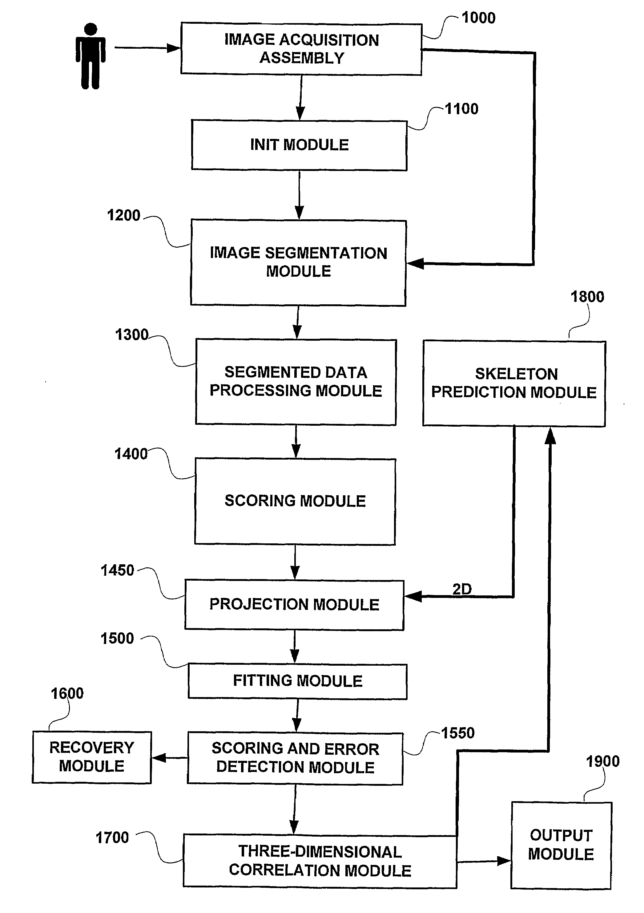
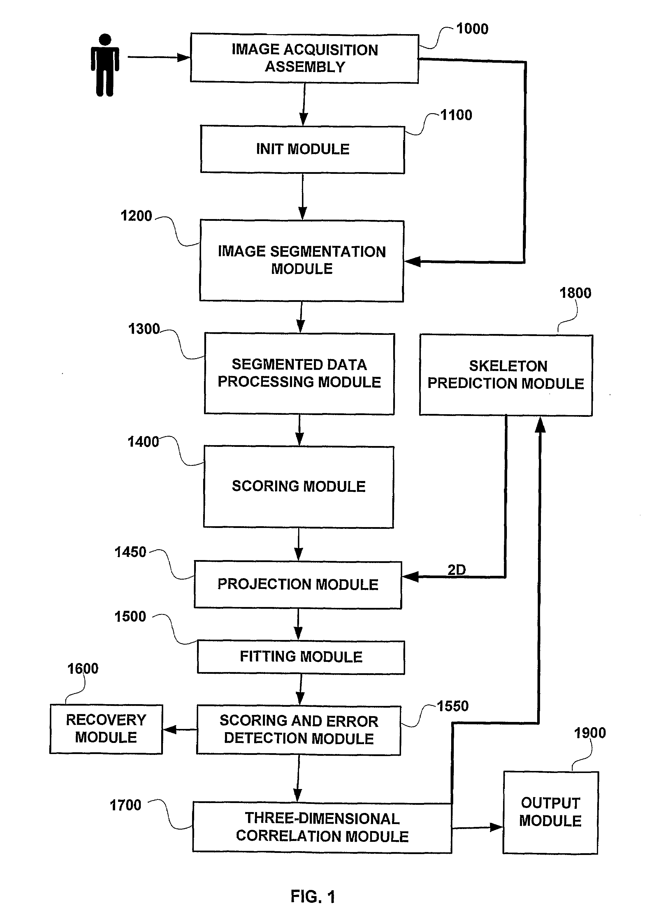
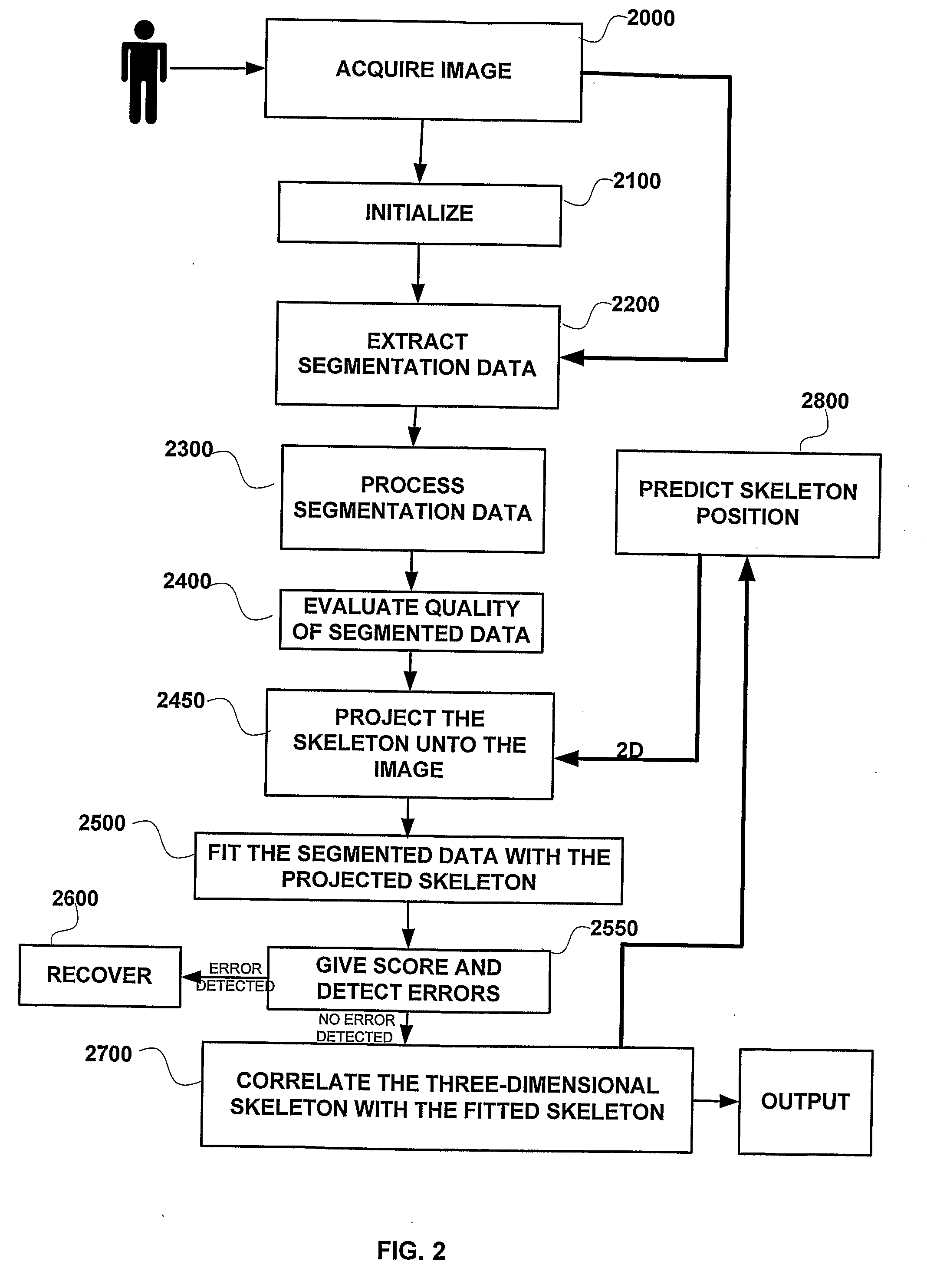
[0055]According to some embodiments of the present invention, the scoring and error detection module may be adapted (1) to examine the processed skeleton after it was associated with segmented data, (2) to evaluate the fitting quality of said skeleton and (3) determine whether an error has occurred during the skeleton prediction process or the association of segmented data.

Problems solved by technology

In the batch era, computing power was extremely scarce and expensive.
Punching the program cards wasn't done on the computer itself, but on specialized typewriter-like machines that were notoriously balky, unforgiving, and prone to mechanical failure.
The software interface was similarly unforgiving, with very strict syntaxes meant to be parsed by the smallest possible compilers and interpreters.
If one were very lucky, it might be hours; real-time response was unheard of.
But there were worse fates than the card queue; some computers actually required an even more tedious and error-prone process of toggling in programs in binary code using console switches.
But these interfaces still placed a relatively heavy mnemonic load on the user, requiring a serious investment of effort and learning time to master.
But until the move to VDTs attached via serial cables, each exceedingly expensive computer could support only one addressable display, on its console.
Under those conditions it was difficult for any tradition of visual UI to develop; such interfaces were one-offs built only in the rare circumstances where entire computers could be at least temporarily devoted to serving a single user.
But at $45M a throw, there were very few actual customers for interactive graphics.
The custom hardware of the NLS / Augment system, while less expensive, was still prohibitive for general use.
Even the PDP1, costing a hundred thousand dollars, was too expensive a machine on which to found a tradition of graphical programming.
But on general-purpose computers, oscilloscope displays became an evolutionary dead end.
Considering the immense changes is in computing and display hardware over the ensuing decades, it has proven surprisingly difficult to think beyond the WIMP.
While the computing power to support these is no longer expensive, the physical display devices still price VR out of general use in 2004.
A more fundamental problem, familiar for many years to designers of flight simulators, is the way VR can confuse the human proprioceptive system; VR motion at even moderate speeds can induce dizziness and nausea as the brain tries to reconcile the visual simulation of motion with the inner ear's report of the body's real-world motions.
This makes them difficult to match with the filesystems and hierarchical namespaces of Unix's architecture, which seems to be one of its most enduring and effective features.

Method used


Image

  • Apparatus system and method for human-machine interface
  • Apparatus system and method for human-machine interface
  • Apparatus system and method for human-machine interface

Examples


Embodiment Construction

[0067]In the following detailed description, numerous specific details are set forth in order to provide a thorough understanding of the invention. However, it will be understood by those skilled in the art that the present invention may be practiced without these specific details. In other instances, well-known methods, procedures, components and circuits have not been described in detail so as not to obscure the present invention.

[0068]Unless specifically stated otherwise, as apparent from the following discussions, it is appreciated that throughout the specification discussions utilizing terms such as “processing”, “computing”, “calculating”, “determining”, or the like, refer to the action and / or processes of a computer or computing system, or similar electronic computing device, that manipulate and / or transform data represented as physical, such as electronic, quantities within the computing system's registers and / or memories into other data similarly represented as physical qua...


PUM


Abstract

There is provided a 3D human machine interface (“3D HMI”), which 3D HMI may include (1) an image acquisition assembly, (2) an initializing module, (3) an image segmentation module, (4) a segmented data processing module, (5) a scoring module, (6) a projection module, (7) a fitting module, (8) a scoring and error detection module, (9) a recovery module, (10) a three dimensional correlation module, (11) a three dimensional skeleton prediction module, (12) an output module and a (13) depth extraction module.

Description

RELATED APPLICATIONS[0001]The present application is a continuation-in-part of:[0002]US.60 / 592,136 filed 30 Jul. 2004[0003]PCT application no. PCT / IL2005 / 000813 filed 31 Jul. 2005[0004]U.S. 60 / 731,274 filed 31 Oct. 2005[0005]U.S. Ser. No. 11 / 227,578 filed 27 Mar. 2006[0006]PCT application no. PCT / IL 2006 / 001254 filed 31 Oct. 2006[0007]Each of which is hereby incorporated by reference in its entirety.FIELD OF THE INVENTION[0008]The present invention generally relates to user interfaces and more particularly to methods and systems of 3D Human-Machine-Interface.BACKGROUND OF THE INVENTION[0009]One of the largest patterns in the history of software is the shift from computation-intensive design to presentation-intensive design. As machines have become more and more powerful, inventors have spent a steadily increasing fraction of that power on presentation. The history of that progression can be conveniently broken into three eras: batch (1945-1968), command-line (1969-1983) and graphica...

Claims


Application Information

Patent Timeline
Patent Type & Authority Applications(United States)
IPC IPC(8): G06T15/00G06K9/34
CPCG06K9/00369G06F3/011G06V40/103G06F3/017G06F3/0304G06T17/00
Inventor GIVON, DOR
Owner EXTREME REALITY
Learn More