Optical vortex retarder micro-array

a technology microarray, which is applied in the field of optical vortex retarder microarray, can solve the problems of difficult control and optimization of the process, a relatively complex procedure relying on the interference of four non-coplanar coherent laser beams, and the method is limited to making single vortex retarder

Inactive Publication Date: 2010-03-18
VIAVI SOLUTIONS INC
View PDF19 Cites 36 Cited by
  • Summary
  • Abstract
  • Description
  • Claims
  • Application Information

AI Technical Summary

Problems solved by technology

While rotating the substrate and / or the orientation of the LPUV light while irradiating the LPP layer has been shown to provide improved vortex retarders, the method is limited to making single vortex retarders.
While the two-dimensional patterning of the LPP layer is conveniently performed with a single step, it is, unfortunately, a relatively complex procedure relying on the interference of four non-coplanar coherent laser beams.
In addition, since the interference pattern is used to provide the two-dimensional patterning it is difficult to control and optimize the process, and in particular, the size of the array, which is limited by the laser spot size and optics.
Moreover, using the interference pattern to provide the two-dimensional patterning introduces intensity modulations which may negatively affect the spatially uniform out-of-plane tilt of the spatially varying fast axis.

Method used


Image

  • Optical vortex retarder micro-array
  • Optical vortex retarder micro-array
  • Optical vortex retarder micro-array

Examples


Embodiment Construction

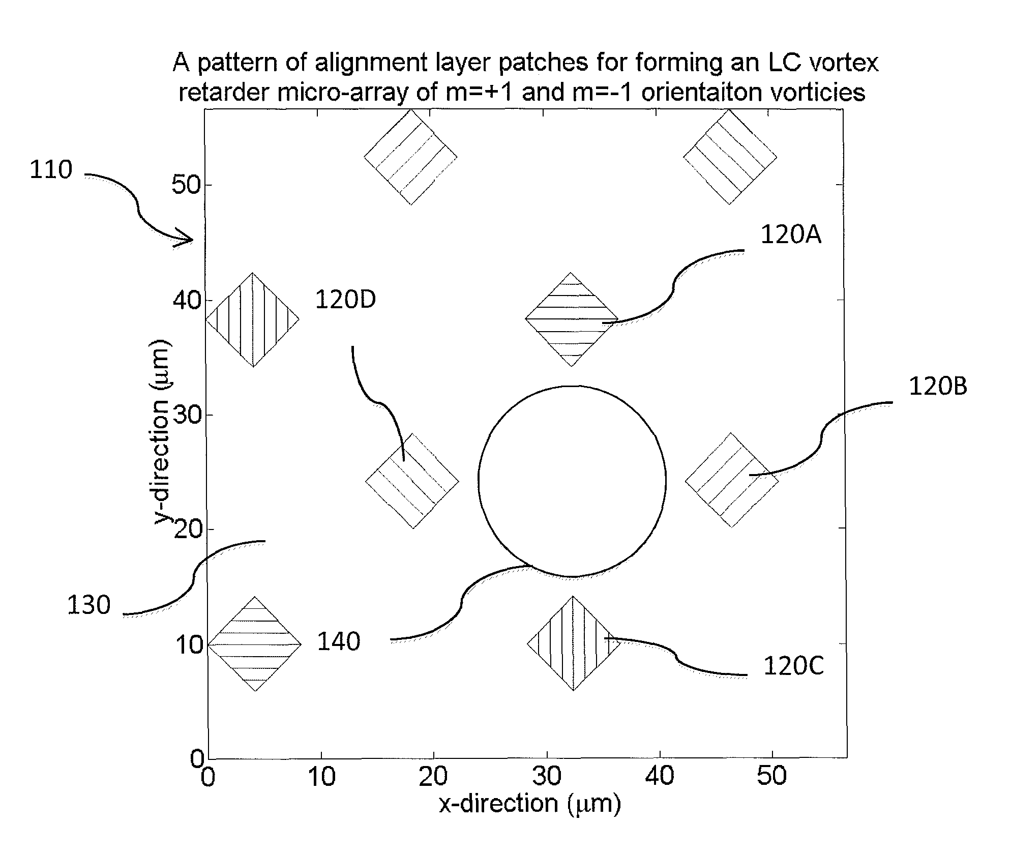
[0043]Referring to FIG. 5A, there is shown a schematic diagram of an alignment layer for creating an array of optical vortex retarders in an adjacent LC or LCP layer, in accordance with one embodiment of the instant invention. The alignment layer 110 includes a plurality of discrete alignment areas or patches 120A, 120B, 120C, 120D interspersed in a substantially non-oriented region 130. Each alignment patch 120A, 120B, 120C, 120D has a fixed aligning orientation that differs from the fixed aligning orientation of one or more other alignment patches. In particular, the plurality of discrete alignment patches 120A, 120B, 120C, 120D includes four different aligning orientations. For example, alignment patch 120A has a fixed aligning orientation that is at 0 degrees, whereas alignment patch 120C has a fixed aligning orientation at 90 degrees, each measured with respect to the x-axis. The plurality of discrete alignment patches 120A, 120B, 120C, 120D is arranged in a predetermined finel...


PUM

PropertyMeasurementUnit
angleaaaaaaaaaa
angleaaaaaaaaaa
diameteraaaaaaaaaa

Abstract

A micro-array of optical vortex retarders is provided by forming an alignment layer having a plurality of discrete alignment patches with different orientations. A layer of birefringent material, including one of a liquid crystal and a liquid crystal polymer precursor material, is provided adjacent to the alignment layer. The aligning orientation and position of each discrete alignment patch in the plurality of discrete alignment patches is selected to induce the layer of birefringent material to form at least one optical vortex retarder adjacent to a substantially non-oriented region of the alignment layer.

Description

CROSS-REFERENCE TO RELATED APPLICATIONS[0001]This application claims priority from U.S. Provisional Application No. 61 / 096,443, filed Sep. 12, 2008, which is hereby incorporated by reference.MICROFICHE APPENDIX[0002]Not Applicable.TECHNICAL FIELD[0003]The present application relates generally to optical vortex retarders and in particular to a micro-array of optical vortex retarders and a method of making the same.BACKGROUND OF THE INVENTION[0004]A waveplate alters polarized light by adding a predetermined phase shift between two orthogonal polarization components of the polarized light field. Conventionally, the added phase shift is referred to as the waveplate retardance and is measured in fractions of a wavelength for normal incident light. For example, a waveplate that adds a phase shift of π between the orthogonal polarizations is referred to as a half-wave plate, whereas a waveplate that adds a phase shift of π / 2 is referred to as a quarter-wave plate.[0005]Traditionally wavepl...

Claims


Application Information

Patent Timeline
Patent Type & Authority Applications(United States)
IPC IPC(8): G02F1/1335G03F7/20
CPCG02B5/3083
Inventor SHEMO, DAVID M.MCELDOWNEY, SCOTT
Owner VIAVI SOLUTIONS INC
Why Eureka
Try Eureka