Liquid crystal display including both color filter and non-color filter regions for increasing brightness

a liquid crystal display and color filter technology, applied in non-linear optics, instruments, optics, etc., can solve the problems of affecting the brightness and contrast of the display, and consuming power. disadvantageously increased,

Inactive Publication Date: 2001-04-10
SHARP KK
View PDF3 Cites 230 Cited by
  • Summary
  • Abstract
  • Description
  • Claims
  • Application Information

AI Technical Summary

Problems solved by technology

However, the backlight consumes about 50% or more of the overall power consumption of the liquid crystal display device, whereby power consumption is disadvantageously increased.
However, brightness and contrast of the display are affected by environmental factors such as brightness around the liquid crystal display device and / or the conditions under which the liquid crystal display device is used.
In the case of the reflection-type liquid crystal display device, visual recognition of the display is affected by environmental factors such as brightness around the liquid crystal display device, and is extremely deteriorated particularly when ambient light is dark.
However, in the case where a conventional color filter is used for color display, optimum color display cannot be obtained both in a transmission mode and reflection mode.
However, Japanese Laid-Open Publication No. 8-286178 merely discloses the structure of the color filter layer for use in a transmission- or reflection-type liquid crystal display device, and fails to disclose an optimal structure of a color filter layer for use in a transmission / refection-type liquid crystal display device including, in every pixel region, both a reflective electrode region for reflecting ambient light and a transmissive electrode region for transmitting light from the backlight.
Therefore, it is very difficult to realize a color filter capable of providing a bright, high color-purity color display both in the transmissive and reflective regions.
Moreover, in the case where a substrate having a color filter layer and a substrate having pixel electrodes are laminated to each other so as to be shifted from each other, that is, in the case where the substrates are mis-aligned with respect to each other, the area of each non-color filter region may vary, thereby reducing display quality.
Therefore, it has been difficult to select a type of pigment and to adjust a concentration of the pigment dispersed in a resin.
In other words, when the ratio of the area of the non-color filter region(s) to the area of the reflective region is set to less than about 0.05, sufficient brightness cannot be obtained in reflection display, resulting in a defective display.
Therefore, light is not absorbed in the color filer substrate, thereby preventing reduction in light utilization efficiency.

Method used


Image

  • Liquid crystal display including both color filter and non-color filter regions for increasing brightness
  • Liquid crystal display including both color filter and non-color filter regions for increasing brightness
  • Liquid crystal display including both color filter and non-color filter regions for increasing brightness

Examples


example 2

Hereinafter, a liquid crystal display device according to Example 2 of the present invention will be described with reference to the drawings. FIGS. 7A and 7B are enlarged plan views each showing a pixel electrode portion of the liquid crystal display device of Example 2.

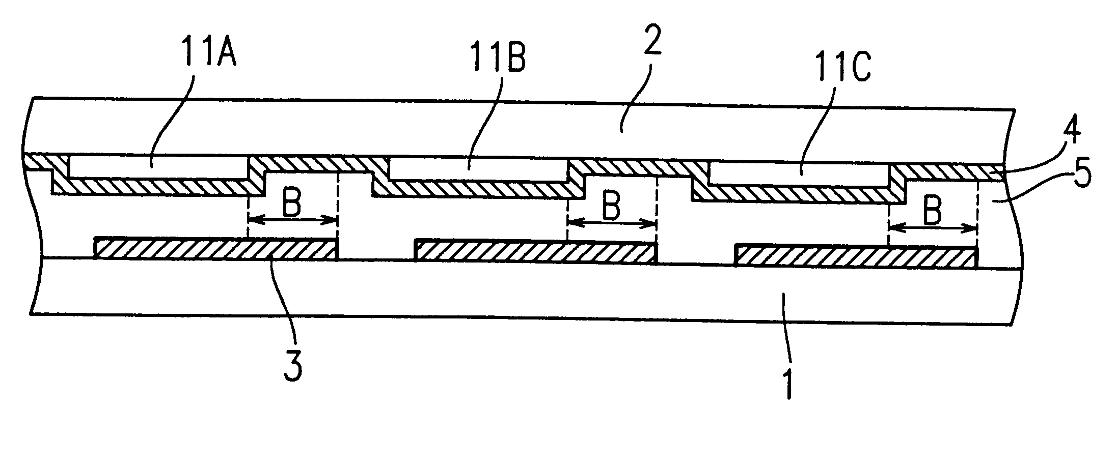
In Example 2, as shown in FIG. 7A, a color filter region 11 of a high color-purity color filter for use in the transmission-type liquid crystal display device is formed as well as non-color filter regions E1 and E2 are provided in each of the regions of the color filter substrate 2 which correspond to the respective picture electrode regions 3. White display is provided by the non-color filter regions E1 and E2, and is mixed with color display provided by the high color-purity color filter regions 11, whereby bright display which is required in the reflective regions of the transmission / reflection-type liquid crystal display device can be realized.

FIG. 7A shows the color filter region 11 on the color filter substrat...

example 3

Hereinafter, a liquid crystal display device according to Example 3 of the present invention will be described with reference to the drawings. FIGS. 8A and 8B are enlarged plan views each showing a pixel electrode portion of the liquid crystal display device of Example 3.

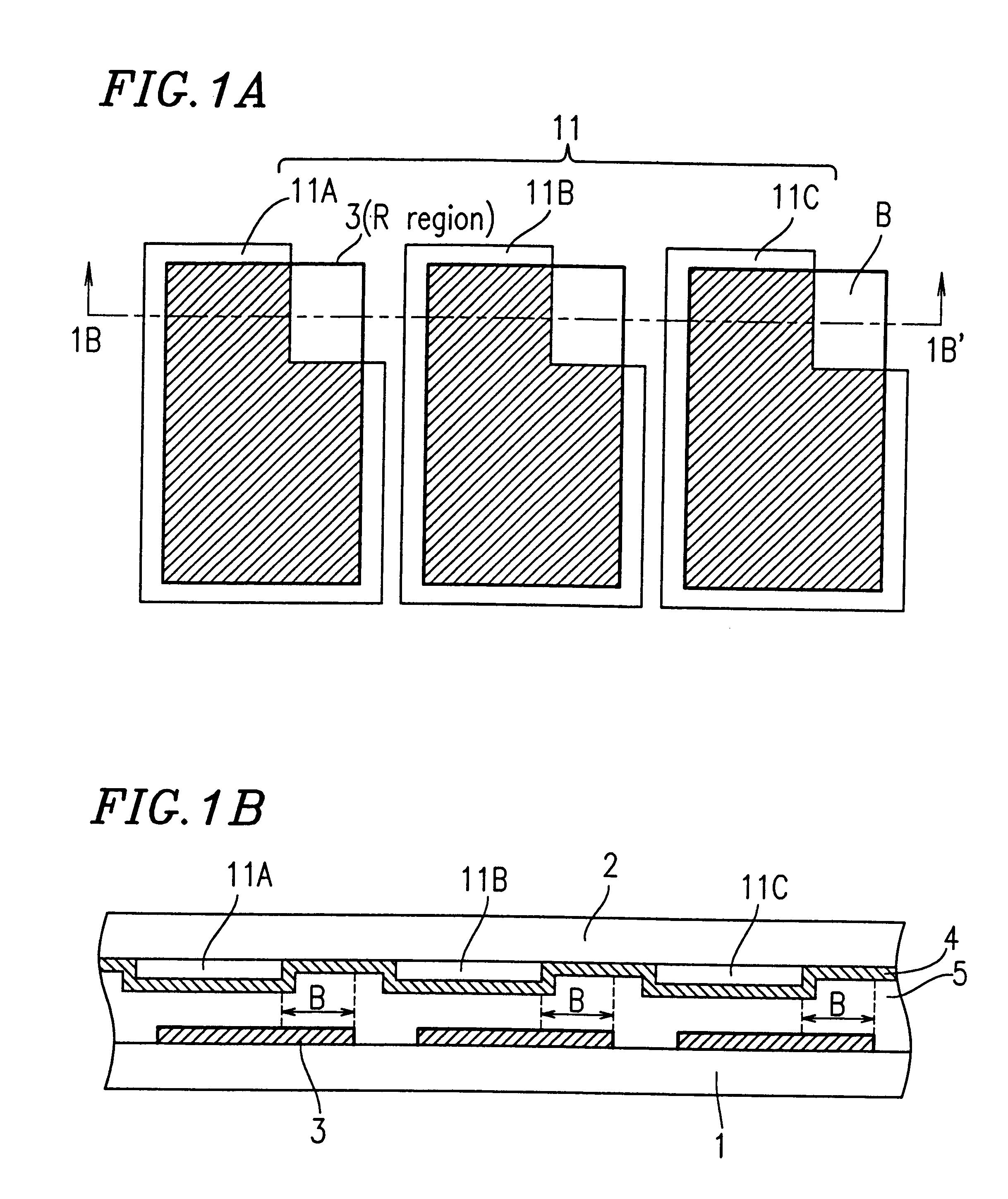
In Example 3, as shown in FIG. 8A, a color filter region 11 of a high color-purity color filter layer for use in the transmission-type liquid crystal display device are formed as well as a non-color filter region F is provided in a region of the color filter substrate which corresponds to the respective pixel electrode 3. White display is provided by the non-color filter regions F, and is mixed with color display provided by the high color-purity color filter regions 11, whereby a bright display, which is required in the reflective regions of the transmission / reflection-type liquid crystal display device, can be realized.

FIG. 8A shows the color filter region 11 on the color filter substrate and the pixel electrode 3...

example 4

Hereinafter, a liquid crystal display device according to Example 4 of the present invention will be described with reference to the drawings. FIGS. 9A and 9B are enlarged plan views each showing a pixel electrode portion of the liquid crystal display device of Example 4.

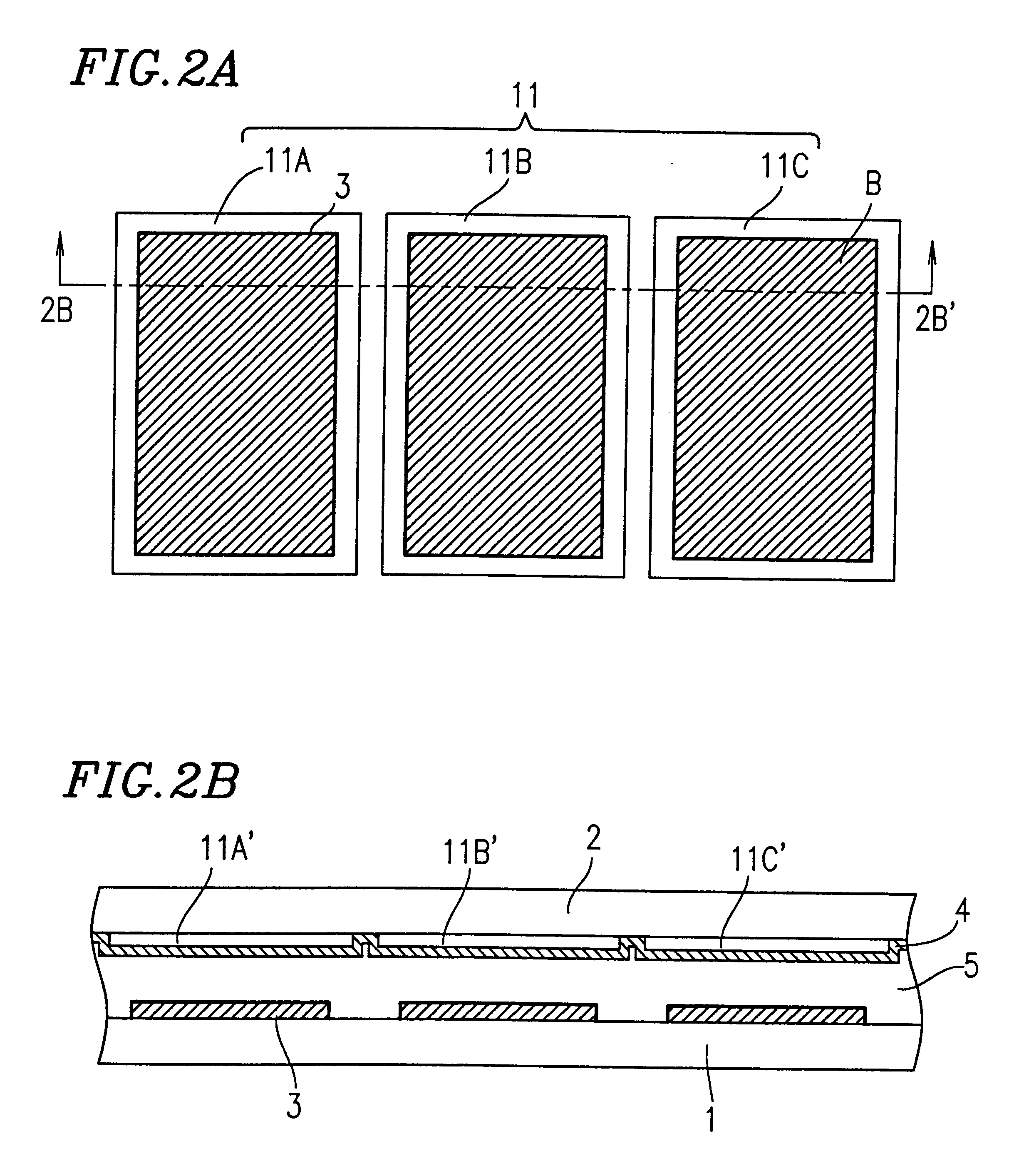
In Example 4, as shown in FIG. 9A, a color filter region 11 of a high color-purity color filter layer for use in the transmission-type liquid crystal display device is formed as well as a non-color filter region G is provided in each of the regions of the color filter substrate which correspond to the respective pixel electrodes 3. White display is provided by the non-color filter regions G, and is mixed with color display provided by the high color-purity color regions 11, whereby a bright display, which is required in the reflective regions of the transmission / reflection-type liquid crystal display device, can be realized.

FIG. 9A shows the color filter region 11 on the color filter substrate 2 and the pixel electr...


PUM

PropertyMeasurementUnit
transmittanceaaaaaaaaaa

Abstract

A liquid crystal display device includes: a first substrate; a second substrate; a liquid crystal layer interposed between the first and second substrates; a plurality of pixel regions for providing a display; and a reflective region for providing a display by using reflected light, the reflective region being provided in each of the plurality of pixel regions, wherein the first substrate includes a reflective electrode region in the reflective region, the second substrate includes a color filter layer, the color filter layer having a color filter region and a non-color filter region in the reflective electrode region, and the color filter region and the non-color filter region are located such that an overlapping area of the reflective electrode region and the non-color filter region is not changed even when the first and second substrates are mis-aligned with respect to each other.

Description

1. Field of the InventionThe present invention relates to a liquid crystal display device for use in office automation (OA) equipment (e.g., word processors and personal computers), portable information equipment (e.g., electronic books), video cassette recorders (VCRs) incorporating a liquid crystal monitor, and the like.2. Description of the Related ArtRecently, liquid crystal display devices have been widely used in OA equipment (e.g., word processors and personal computers), portable information equipment (e.g., electronic books), video cassette recorders (VCRs) incorporating a liquid crystal monitor and the like, utilizing the features of a thin display thickness and low power consumption.Such liquid crystal display devices include a transmission-type liquid crystal display device using a thin, transparent, electrically conductive film such as ITO (Indium Tin Oxide) as pixel electrodes, and a reflection-type liquid crystal display device using reflective electrodes of, for exam...

Claims


Application Information

Patent Timeline
Patent Type & Authority Patents(United States)
IPC IPC(8): G02F1/13G02F1/1335
CPCG02F1/133514G02F1/133555
Inventor NARUTAKI, YOZOKUBO, MASUMIFUJIOKA, SHOGOSHIMADA, TAKAYUKIKATAYAMA, MIKIOYOSHIMURA, YOUJIISHII, YUTAKA
Owner SHARP KK
Why Eureka
Try Eureka