Process for roll-to-roll manufacture of a display by synchronized photolithographic exposure on a substrate web

a technology of photolithographic exposure and substrate web, which is applied in the field of electrophoretic displays, can solve the problems of difficult to keep different colors of suspensions from each other in the partition-type electrophoretic display, and the production of electrophoretic displays by the microencapsulation process, and achieves the effects of low cost production, high volume and efficient and inexpensive production

Inactive Publication Date: 2002-12-05
E INK CALIFORNIA
View PDF18 Cites 230 Cited by
  • Summary
  • Abstract
  • Description
  • Claims
  • Application Information

AI Technical Summary

Benefits of technology

0031] Because these multiple-step processes as disclosed may be carried out roll-to-roll continuously or semi-continuously, they are suitable for high volume and low cost production. These processes are also efficient and inexpensive as compared to other processes for high volume production operations. The electrophoretic display prepared according to the present invention is not sensitive to environment, such as humidity and temperature. The display is thin, flexible, durable, easy-to-handle, and format-flexible. Since the electrophoretic displ

Problems solved by technology

However, in the case of the partition-type electrophoretic display, some difficulties are encountered in the formation of the partitions and the process of enclosing the suspension.
Furthermore, it is also difficult to keep different colors of suspensions separate from each other in the partition-type electrophoretic display.
For example, the electrophoretic displays manufactured by the microencapsulation process suffer from sensitivity to environmental changes (in particular sensitivity to moisture and temperature) due to the wall chemistry of the microcapsules.
Secondly the electrophoretic displays based on the microcapsules have poor scratch resistance due to the thin wall and large particle size of the microcapsules.
To improve the handle ability of the di

Method used


Image

  • Process for roll-to-roll manufacture of a display by synchronized photolithographic exposure on a substrate web
  • Process for roll-to-roll manufacture of a display by synchronized photolithographic exposure on a substrate web
  • Process for roll-to-roll manufacture of a display by synchronized photolithographic exposure on a substrate web

Examples


example 12

[0097] Example 12 Preparation Of The Radiation-Curable Cup Material. 12 Parts of Ebecryl 600 (UCB Chemicals, Smyrna, GA), 2.7 parts of Ebecryl 4827, 1 part of Ebecryl 1360, 6 parts of HDDA (UCB Chemicals), and 1 part of Irgacure 500 (Ciba Specialty Chemicals, Tarrytown, NY), were mixed homogeneously with 5 parts of methyl ethyl ketone (MEK). The solution was coated onto an ITO / PET film by Myrad bar with a target dry thickness of 50 microns. The coated sample was then exposed through a mask and developed with isopropanol.

[0098] Example 13 Preparation Of The Radiation-Curable Cup Material. The same as Example 12, except the formulation was replaced by 12 parts of Ebecryl 830, 5.5 parts of SR399 (Sartomer, Exton, PA), 2 parts of HDDA, 0.488 parts of Ebecryl 1360, 0.1v parts of Irgacure 369 (Ciba Specialty Chemicals), 0.02 parts of isopropyl thioxanthone (ITX) from Aldrich, and 10 parts of MEK.

[0099] Example 14 Preparation Of The Radiation-Curable Cup Material. The same as Example 13, e...


PUM

PropertyMeasurementUnit
Coloraaaaaaaaaa
Sizeaaaaaaaaaa
Shapeaaaaaaaaaa

Abstract

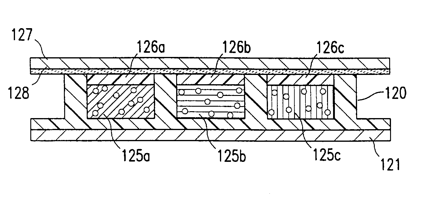
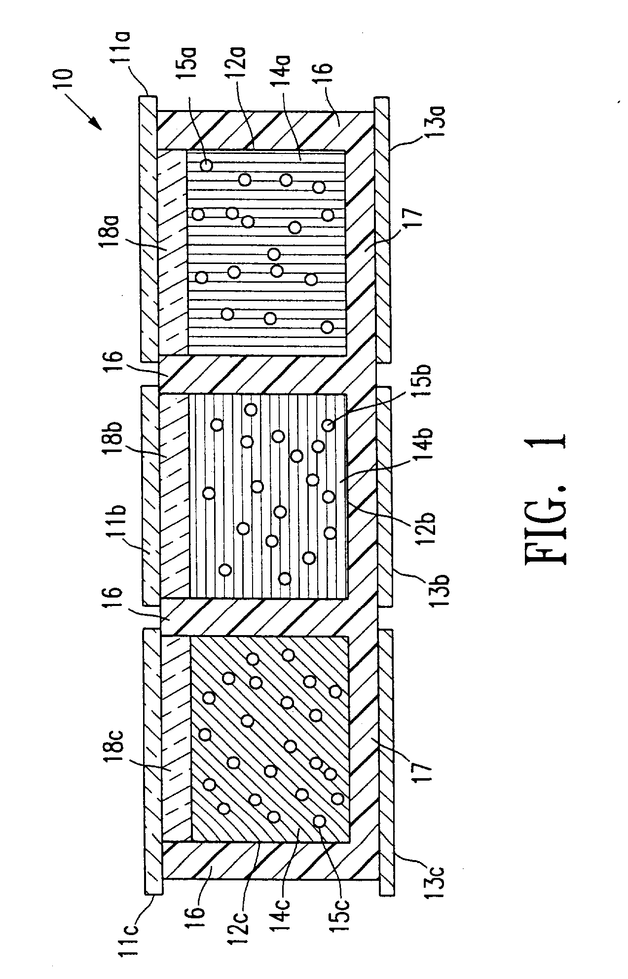
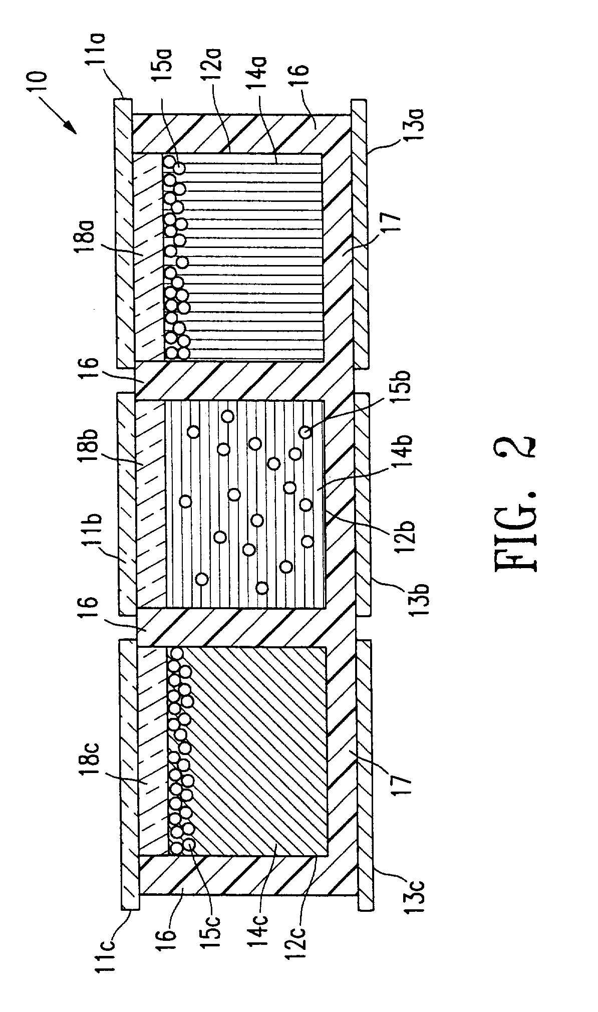
<heading lvl="0">Abstract of Disclosure</heading> This invention relates to an electrophoretic display or a liquid crystal display and novel processes for its manufacture. The electrophoretic display (EPD) of the present invention comprises microcups of well-defined shape, size and aspect ratio and the microcups are filled with charged pigment particles dispersed in an optically contrasting dielectric solvent. The liquid crystal display (LCD) of this invention comprises well-defined microcups filled with at least a liquid crystal composition having its ordinary refractive index matched to that of the isotropic cup material. A novel roll-to-roll process and apparatus of the invention permits the display manufacture to be carried out continuously by a synchronized photo-lithographic process. The synchronized roll-to-roll process and apparatus permits a pre-patterned photomask, formed as a continuous loop, to be rolled in a synchronized motion in close parallel alignment to a web which has been pre-coated with a radiation sensitive material, so as to maintain image alignment during exposure to a radiation source. The radiation sensitive material may be a radiation curable material, in which the exposed and cured portions form the microcup structure. In an additional process step, the radiation sensitive material may be a positively working photoresist which temporarily seals the microcups. Exposure of a selected subset of the microcups via the photomask image permits selective re-opening, filling and sealing of the microcup subset. Repetition with additional colors permits the continuous assembly of a multicolor EPD or LCD display.

Description

Description[0001] RELATED APPLICATIONS: The present application is a Continuation-In-Part of US Patent Application No. 09 / 518,488, filed March 3, 2000, and of US Patent Application No. 09 / 606,654, filed June 28, 2000, and of the US Patent Application No. 09 / 759,212, filed January 11, 2001 by the same inventive entity. Each of the above referenced patent applications is incorporated by reference herein and the benefit of the filing date of each application is hereby claimed under 35 U.S.C. Section 1.20. This application is one of series of our co-pending applications by the same inventive entity pertaining to novel electrophoretic and LCD image displays and subassemblies, and to novel methods of making such displays and subassemblies. Certain of the inventions which are disclosed in these related applications are also disclosed in the present application. The absence of claims in the present application directed to any particular inventive subject matter disclosed herein is not to be...

Claims


Application Information

Patent Timeline
IPC IPC(8): G02F1/1333G02F1/167G02F1/16755G02F1/1679
CPCG02F1/133305G02F1/167G02F1/133377G02F1/16755G02F1/1679
Inventor CHAN-PARK , MARYCHEN , XIANHAIWU , ZARNG-ARH GEORGEWANG , XIAOJIAZANG , HONG-MEILIANG , RONG-CHANG
Owner E INK CALIFORNIA
Why Eureka
Try Eureka