CMC Vane Assembly Apparatus and Method

Active Publication Date: 2010-03-18
SIEMENS ENERGY INC
View PDF18 Cites 181 Cited by
  • Summary
  • Abstract
  • Description
  • Claims
  • Application Information

AI Technical Summary

Problems solved by technology

Thus, problems arise in assembling vanes with both the required mechanical strength and thermal endurance.
However forming CMC airfoils by wet layering on a metal core is unsatisfactory, because curing of CMC requires temperatures that damage metal.
CMC or superalloy airfoils may be formed separately and then assembled over the metal core, but this involves problems with assembly.
If an inner and outer platform and vane core are cast integrally, there is no way to slide CMC cover elements over them.
However,

Method used


Image

  • CMC Vane Assembly Apparatus and Method
  • CMC Vane Assembly Apparatus and Method
  • CMC Vane Assembly Apparatus and Method

Examples


Embodiment Construction

[0015]The inventors devised a vane assembly that can be fabricated using conventional metal casting and CMC fabrication, can be assembled with sufficient mechanical strength and thermal endurance, and accommodates differential thermal expansion, thus solving the above problems of the prior art. It limits stresses on the CMC airfoil to wall thickness compressive stresses, which are best for CMC, and it also provides an easily replaceable CMC vane airfoil.

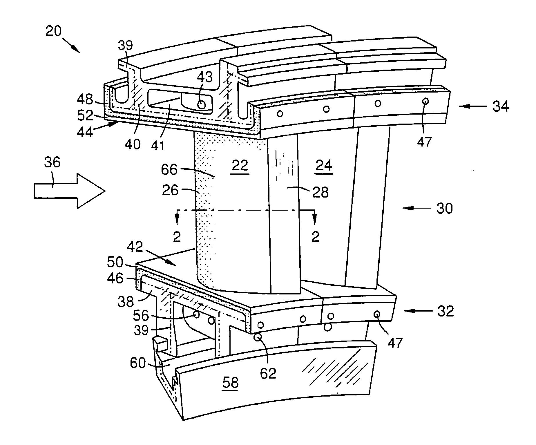
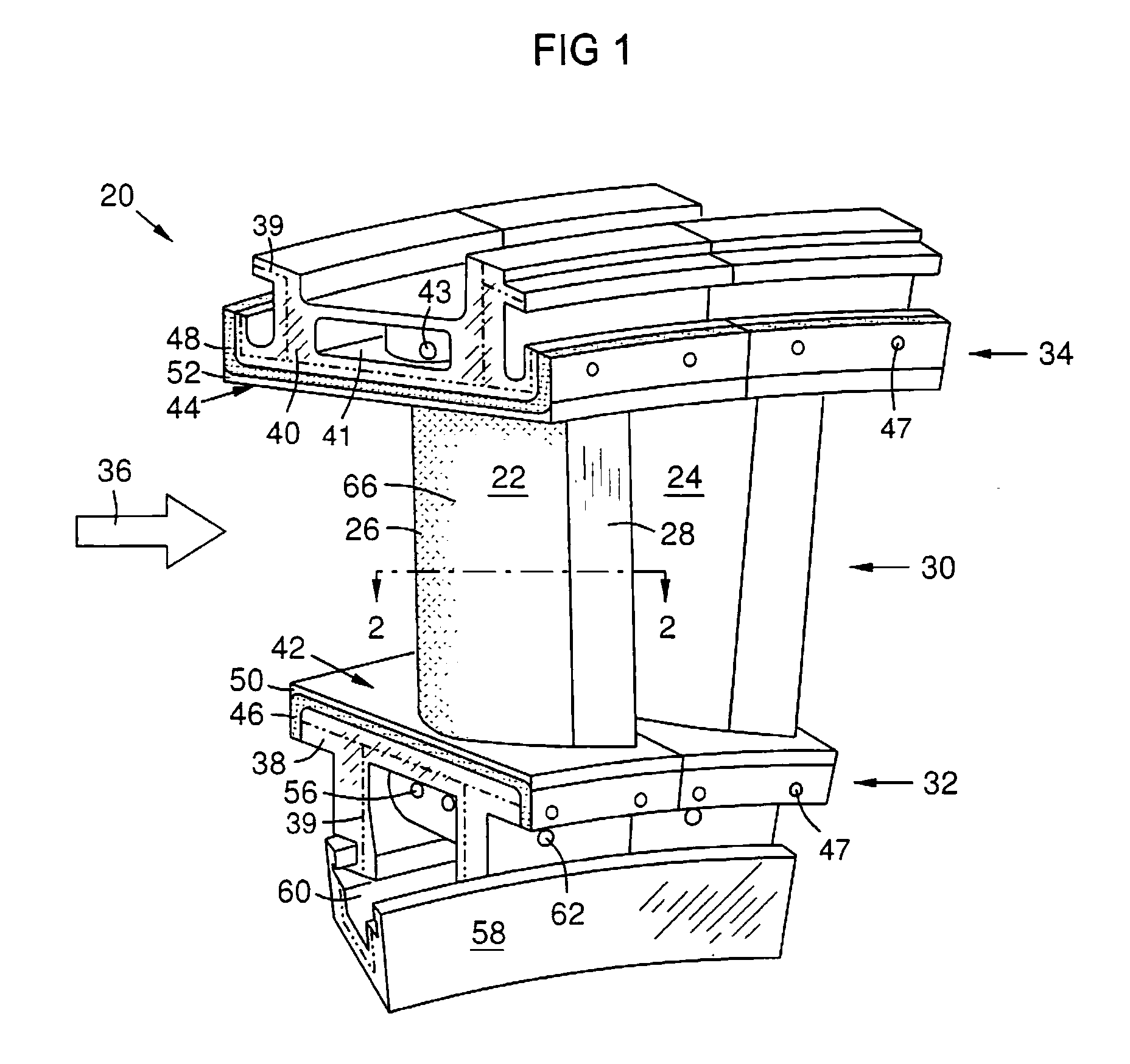
[0016]FIG. 1 shows an assembly of two stationary turbine vanes 22, 24 that are part of a circular array 30 of turbine vanes positioned between inner and outer shroud rings 32, 34. A hot working gas 36 passes through the annular path between the inner and outer shroud rings 32, 34, and over the vanes 30, which direct the gas flow 36 for optimal aerodynamic action against adjacent rotating turbine blades (not shown). Each shroud ring 32, 34 is formed of a series of arcuate platforms or backing plates 38, 40. Each turbine vane 22, 24 ha...


PUM

PropertyMeasurementUnit
Lengthaaaaaaaaaa
Pressureaaaaaaaaaa

Abstract

A metal vane core or strut (64) is formed integrally with an outer backing plate (40). An inner backing plate (38) is formed separately. A spring (74) with holes (75) is installed in a peripheral spring chamber (76) on the strut. Inner and outer CMC shroud covers (46, 48) are formed, cured, then attached to facing surfaces of the inner and outer backing plates (38, 40). A CMC vane airfoil (22) is formed, cured, and slid over the strut (64). The spring (74) urges continuous contact between the strut (64) and airfoil (66), eliminating vibrations while allowing differential expansion. The inner end (88) of the strut is fastened to the inner backing plate (38). A cooling channel (68) in the strut is connected by holes (69) along the leading edge of the strut to peripheral cooling paths (70, 71) around the strut. Coolant flows through and around the strut, including through the spring holes.

Description

CROSS-REFERENCE TO RELATED APPLICATIONS[0001]Applicants claim the benefit of U.S. provisional patent applications 61 / 097,927 and 61 / 097,928, both filed on Sep. 18, 2008, and incorporated by reference herein.STATEMENT REGARDING FEDERALLY SPONSORED DEVELOPMENT[0002]Development for this invention was supported in part by Contract No. DE-FC26-05NT42646, awarded by the United States Department of Energy. Accordingly, the United States Government may have certain rights in this invention.FIELD OF THE INVENTION[0003]This invention relates to a combustion turbine vane assembly with a metal vane core and a ceramic matrix composite (CMC) or superalloy airfoil sheath on the core, the core and airfoil spanning between metal backing plates, the plates forming segments of inner and outer shrouds surrounding an annular working gas flow path. The invention also relates to ceramic matrix composite or superalloy shroud covers.BACKGROUND OF THE INVENTION[0004]Combustion turbines include a compressor a...

Claims


Application Information

Patent Timeline
IPC IPC(8): F01D25/12F01D9/02B23P11/00
CPCF01D5/189F01D5/282F01D5/284F01D9/041F05D2300/21F05D2300/603Y10T29/49323
Inventor SCHIAVO, ANTHONY L.GONZALEZ, MALBERTO F.HUANG, KUANGWEIRADONOVICH, DAVID C.
Owner SIEMENS ENERGY INC
Why Eureka
Try Eureka