
Electronic devices and methods that communicate via transferjet and NFC transmitter and receiver pairing

Active Publication Date: 2010-03-18
SONY CORP
View PDF1 Cites 71 Cited by
  • Summary
  • Abstract
  • Description
  • Claims
  • Application Information

AI Technical Summary

Benefits of technology

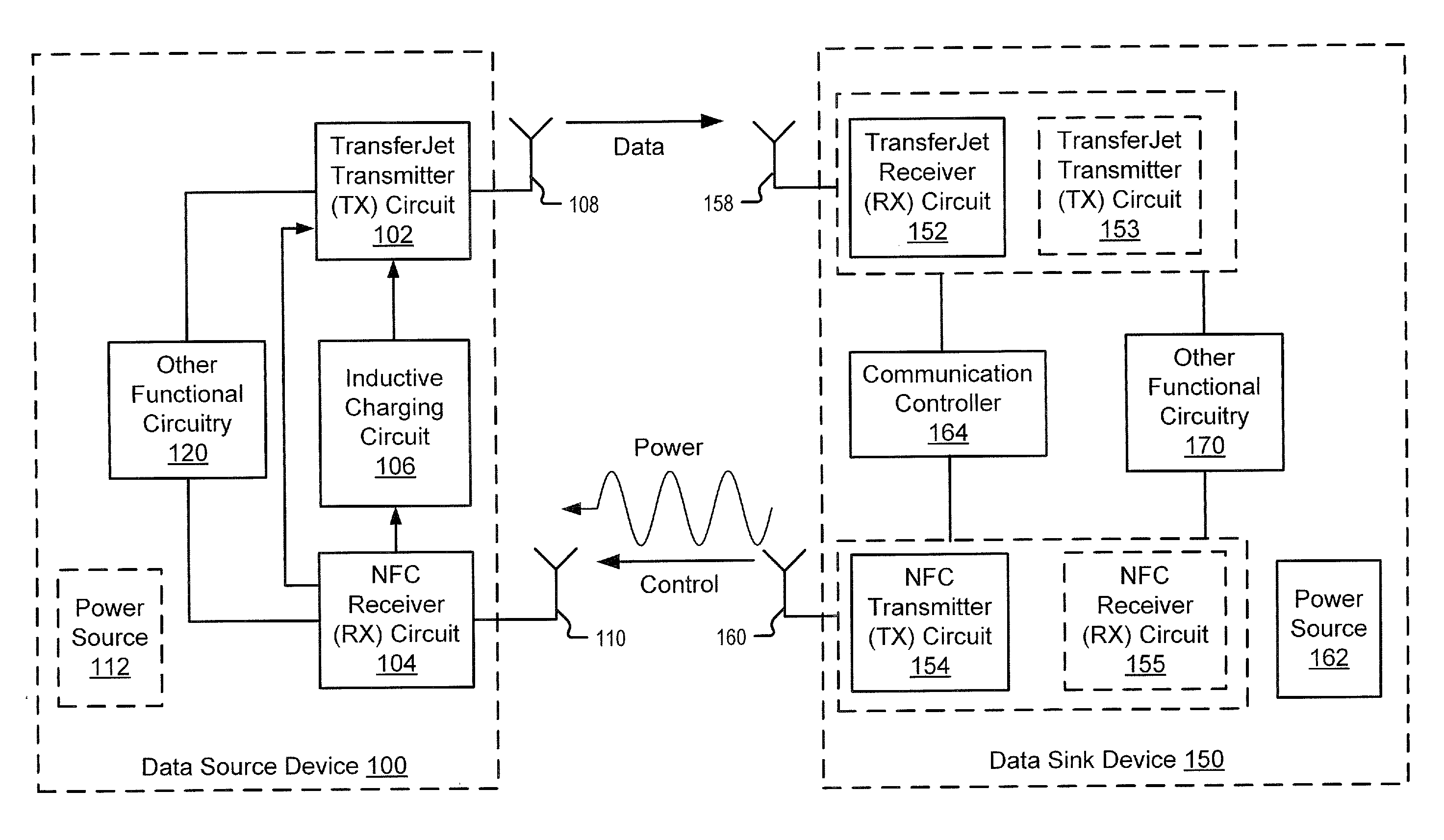
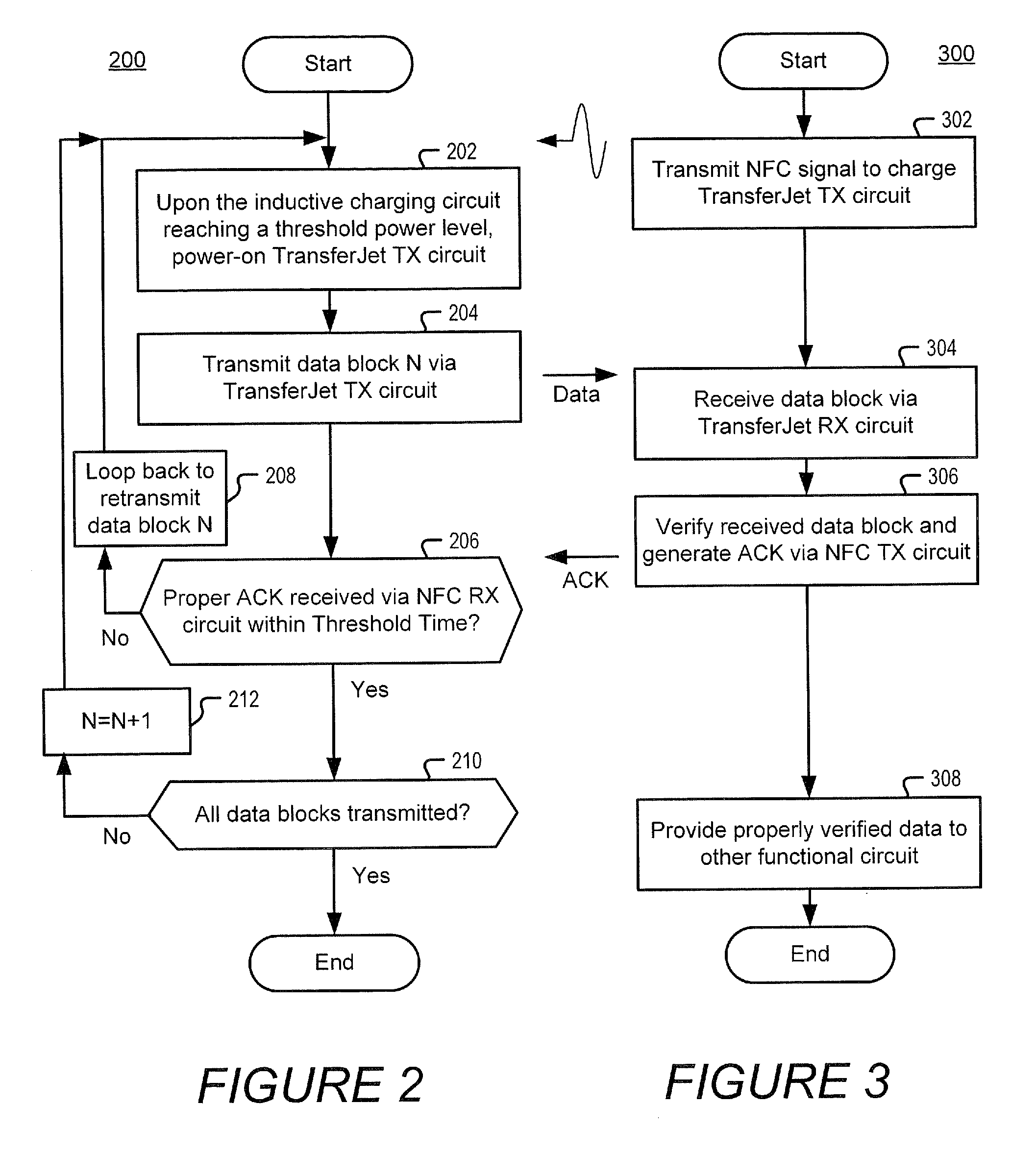
[0009]The high-rate RF wirelesstransmitter circuit may be further configured to increase a time delay between transmission RF bursts in response to the communication control signal, which is received via magnetic coupling through the low-rate magnetically coupled, indicating that the previously transmitted block of data was not properly received by the other proximately located communication device. Increasing the time delay can cause the charging circuit to accumulate power over a longer time between burst transmissions.
[0015]The communication controller may be further configured to respond to a failed verification outcome by further delaying an upcoming transmission of a data block from the other proximately located communication device. The communication controller can thereby allow an inductive charging circuit in the other proximately located communication device to accumulate more stored power from magnetic signals from the low-rate magnetically coupled transmitter circuit.
[0018]The communication controller may be further configured to determine a signal power level of the data block received by the high-rate RF wireless receiver circuit, and to control the length of a delay time between receipt of the data block and transmission of the corresponding communication control signal to the other proximately located communication device in response to the outcome of the determined signal power level. The communication controller may thereby control an amount of power that is stored between high-rate RF wireless transmissions by an inductive charging circuit in the other proximately located communication device from magnetic signals transmitted by the low-rate magnetically coupled transmitter circuit.

Problems solved by technology

The high-rate RF wirelesstransmitter circuit may consume power at a greater rate when transmitting than what can be generated by the charging circuit from the magnetic signals.

Method used


Image

  • Electronic devices and methods that communicate via transferjet and NFC transmitter and receiver pairing
  • Electronic devices and methods that communicate via transferjet and NFC transmitter and receiver pairing
  • Electronic devices and methods that communicate via transferjet and NFC transmitter and receiver pairing

Examples


Embodiment Construction

[0028]The present invention now will be described more fully hereinafter with reference to the accompanying figures, in which embodiments are shown. This invention may, however, be embodied in many alternate forms and should not be construed as limited to the embodiments set forth herein.

[0029]Accordingly, while the invention is susceptible to various modifications and alternative forms, specific embodiments thereof are shown by way of example in the drawings and will herein be described in detail. It should be understood, however, that there is no intent to limit the invention to the particular forms disclosed, but on the contrary, the invention is to cover all modifications, equivalents, and alternatives falling within the spirit and scope of the invention as defined by the claims. Like numbers refer to like elements throughout the description of the figures.

[0030]The terminology used herein is for the purpose of describing particular embodiments only and is not intended to be lim...


PUM


Abstract

An electronic communication device includes a high-rate RF wireless transmitter circuit (e.g., a TransferJet transmitter circuit) and a low-rate magnetically coupled receiver circuit (e.g., a Near Field Communication receiver circuit). The high-rate RF wireless transmitter circuit transmits a block of data to another proximately located communication device via RF signals using a first RF communication protocol. The low-rate magnetically coupled receiver circuit receives a communication control signal from the other proximately located communication device via magnetic coupling thereto using a second protocol that is different from the first RF communication protocol, and responds to the communication control signal by selectively triggering the high-rate RF wireless transmitter circuit to transmit another block of data when available for transmission.

Description

BACKGROUND OF THE INVENTION[0001]This invention relates to electronic wireless communication devices and, more particularly, to near field communication devices and operating methods therefor.[0002]Near Field Communication or NFC, is a short-range high frequency wireless communication technology which enables the exchange of data between devices over about a 10 cm distance. The communication protocol and operation is an extension of the ISO 14443 proximity-card standard (contactless card, RFID) and is specified in the ECMA-340 and ISO / IEC 18092 technology standards. NFC is used in some devices to combine the interface of a smartcard and a reader into a single device. An NFC device may communicate with both existing ISO 14443 smartcards and readers, as well as with other NFC devices, and is thereby compatible with existing contactless communication infrastructure.[0003]Like ISO 14443, NFC devices communicate via magnetic field induction. Loop antennas in the devices are placed in clo...

Claims


Application Information

Patent Timeline
IPC IPC(8): H04B5/00
CPCH04B5/0025H04B5/02H04B5/0037H04B5/0031H04B5/70H04B5/48H04B5/72H04B5/79
Inventor HAARTSEN, JACOBUS CORNELIS
Owner SONY CORP
Learn More