Methods and Apparatus For Self-Jamming Suppression In A Radio Frequency Identification (RFID) Reader

Inactive Publication Date: 2010-03-18
TRIMBLE NAVIGATION LTD
View PDF16 Cites 48 Cited by
  • Summary
  • Abstract
  • Description
  • Claims
  • Application Information

AI Technical Summary

Benefits of technology

[0008]Also, changes in the RFID reader's operating frequency can be monitored so the transmitter-receiver isolation circuit may be “retuned” to optimally tune out the self-jammer energy. In addition, signals at the input of the receiver's demodulator or mixer can be monitored. In response to the monitored signals, the transmitter-receiver isolation circuit is “retuned” to minimize the radio frequency (RF) energy due to the self jammer that is present at the input of the receiver's demodulator or mixer. Also, signals at the output of the receiver's demodulator or mixer are monitored and used to “retune” the transmitter-receiver isolation circuit to minimize the DC offset at the output of the receiver's demodulator or mixer caused by the self-jammer energy multiplying against the reader's local oscillator.
[0009]Also, signals at the output of the receiver's demodulator or mixer are measured and used to retune the transmitter-receiver isolation circuit to minimize the baseband noise caused by the self-jammer energy multiplying against the reader's local oscillator. In addition, cer

Problems solved by technology

Passive RFID reader systems present design challenges because the reader's transmitter and receiver must be simultaneously active.
This simultaneous transmission and reception poses a particular challenge for the receiver section of the RFID r

Method used


Image

  • Methods and Apparatus For Self-Jamming Suppression In A Radio Frequency Identification (RFID) Reader
  • Methods and Apparatus For Self-Jamming Suppression In A Radio Frequency Identification (RFID) Reader
  • Methods and Apparatus For Self-Jamming Suppression In A Radio Frequency Identification (RFID) Reader

Examples


Example

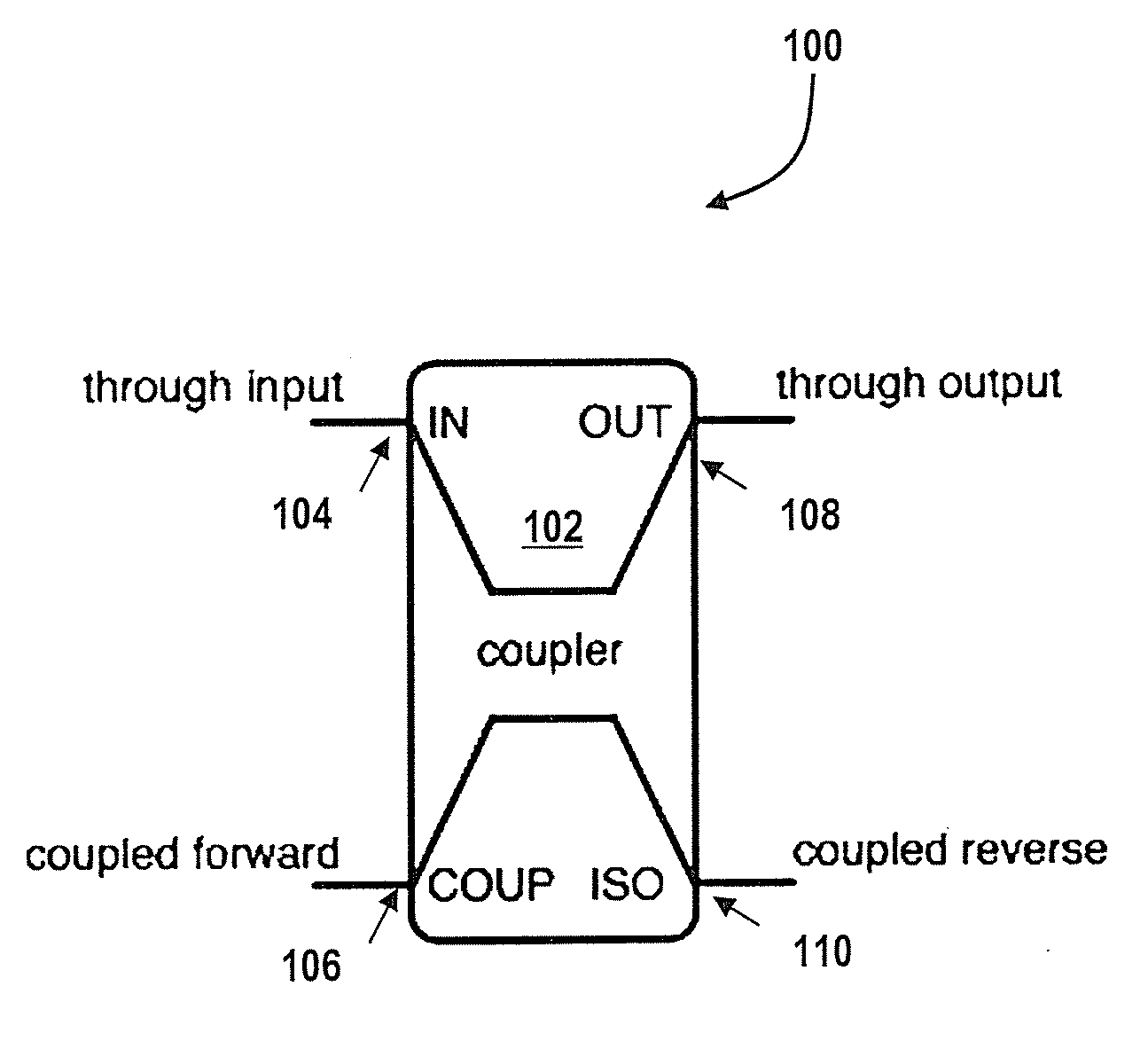
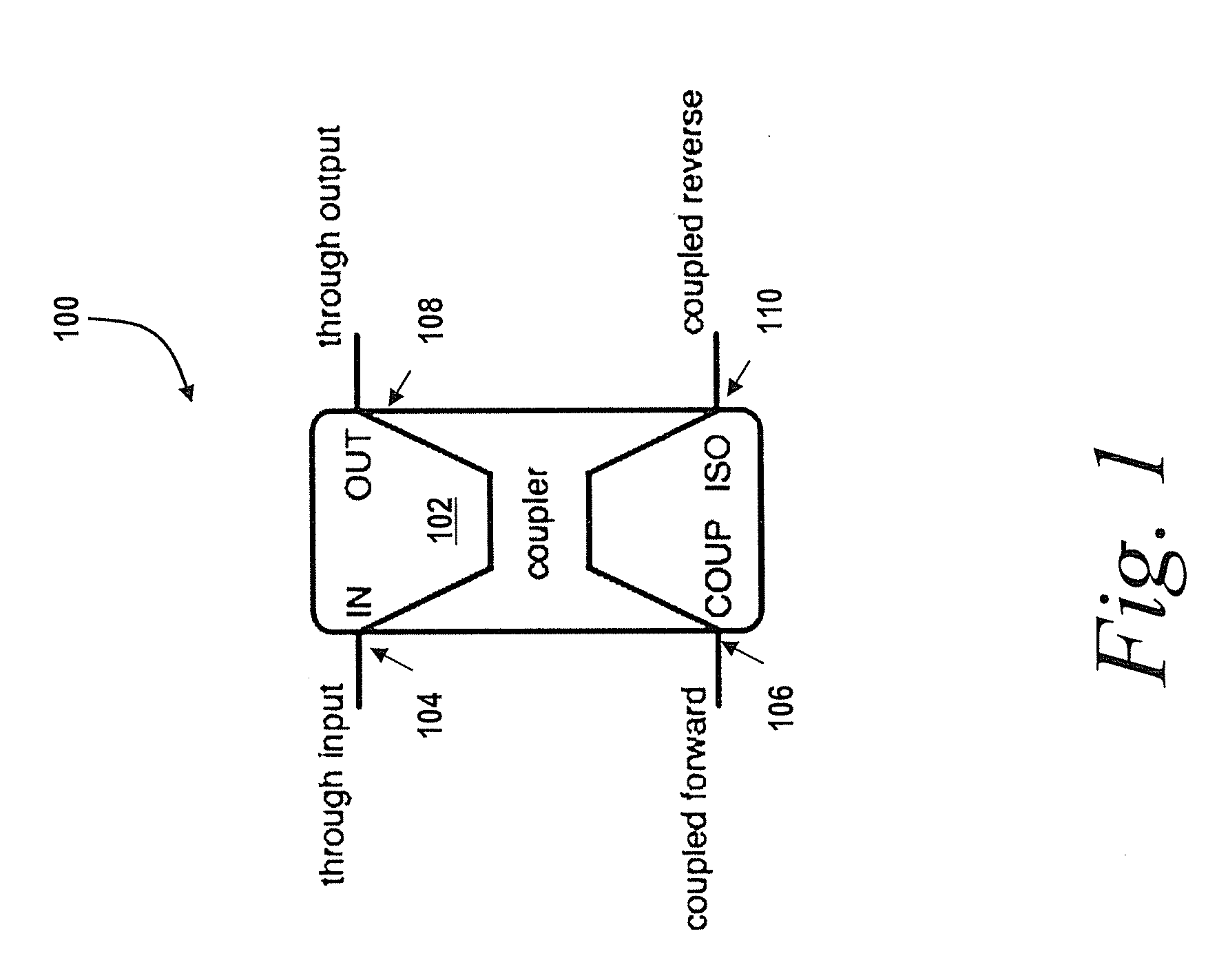
[0022]Referring now to FIG. 1, an isolation circuit 100 is shown and described. In one embodiment, the isolation circuit 100 is a transmitter-receiver isolation circuit that is based on a single directional coupler 102. A directional coupler is a device that preferentially couples signals to different output ports depending on the direction of travel of signals through the main path of the directional coupler. In a specific embodiment, the isolation circuit 100 includes a directional coupler with the coupling among the two output ports relative to the direction of travel of signals along the main path of the directional coupler.

[0023]In a well known configuration of an RFID reader, a directional coupler's “through input” port 104 is typically connected to the RFID reader's transmitter. The “through output” port 108 is typically connected to an antenna (not shown). The “coupled forward” port 106 is typically terminated in a matched load resistance (not shown), for example a 50-ohm re...


PUM


Abstract

A circuit for transmitter-receiver isolation that is useful in a monostatic (combined transmitting and receiving) antenna configuration is shown and described. In addition, methods and systems are shown for automatically adjusting the circuit in response to changes in antenna configuration, external signal reflectors, and jamming energy (e.g., self jammer energy) by adjusting the circuit to tune out these sources of jammer energy to yield an increase in RFID reader receiver sensitivity when compared to measurements of the receiver sensitivity when the jammer energy is not present.

Description

RELATED APPLICATION[0001]This application is related to and claims priority to the following U.S. provisional application, which is incorporated by reference in its entirety: “METHODS AND APPARATUS FOR JAMMING SUPPRESSION IN AN RFID READER,” U.S. Provisional Application No. 60 / 912,871, filed Apr. 19, 2007.FIELD OF THE INVENTION[0002]The present disclosure relates generally to a radio frequency identification (RFID) reader. More specifically, it relates to systems and methods for suppressing a jamming signal coupled from a transmitter to a receiver of an RFID reader.BACKGROUND OF THE INVENTION[0003]Passive RFID reader systems present design challenges because the reader's transmitter and receiver must be simultaneously active. This is because the reader's transmitted signal is used to power the tag, and this power must remain available for the tag to be powered up when responding to the reader's commands. An RFID reader, in some cases, receives a weak reply signal from a passive tag ...

Claims


Application Information

Patent Timeline
IPC IPC(8): H04B15/00H04Q5/22
CPCG06K7/0008H04B15/04H04K2203/20H04K3/28H04B2215/064
Inventor CARRICK, JOHN C.HEROLD, ROBERT R.KRISHNA, SRIREYNOLDS, MATTHEWMAGUIRE, YAEL G.PAPPU, RAVIKANTH
Owner TRIMBLE NAVIGATION LTD
Why Eureka
Try Eureka