Eureka AIR delivers breakthrough ideas for toughest innovation challenges, trusted by R&D personnel around the world.

Air-conditioning algorithm for water terminal free cooling

Inactive Publication Date: 2010-03-18
CARRIER CORP
View PDF16 Cites 16 Cited by
  • Summary
  • Abstract
  • Description
  • Claims
  • Application Information

AI Technical Summary

Benefits of technology

[0012]An air-conditioning system control scheme is provided for implementation in local water terminals of a building air conditioning system wherein each water terminal can receive a command from a building management system to run in a variety of modes to achieve energy savings and increased water terminal cooling capacity. These modes are dependent on the temperature of the outside air measurement provided to the building management system, the local zone temperature setpoints, and the human occupancy of the air-conditioned zone.
[0015]In one embodiment, a new water terminal control scheme achieves energy savings and free cooling of a building zone by accepting a command from a building management system to run in the free cooling mode.
[0016]In another embodiment, a new water terminal control scheme achieves energy savings and pre-free cooling of a building zone by accepting a command from a building management system to run in the pre-free cooling mode.

Problems solved by technology

However, this control scheme does not take advantage of information relating to the condition of the outside air to create energy savings.
This is problematic because achievement of the desired zone temperature may be beyond the capacity of the water terminal because the outside air temperature is largely different than the zone setpoint and opening the fresh air damper may result in a change in zone temperature that is even further away from the setpoint.
While most systems use the local water terminal controller to control the air temperature, and the carbon dioxide system to control the carbon dioxide dilution in the zone by actuating their fresh air dampers, they do not employ additional sensors or controls to optimize the system by making full use of the combined information relating to the carbon dioxide dilution and outside air conditions.

Method used


Image

  • Air-conditioning algorithm for water terminal free cooling
  • Air-conditioning algorithm for water terminal free cooling
  • Air-conditioning algorithm for water terminal free cooling

Examples


Embodiment Construction

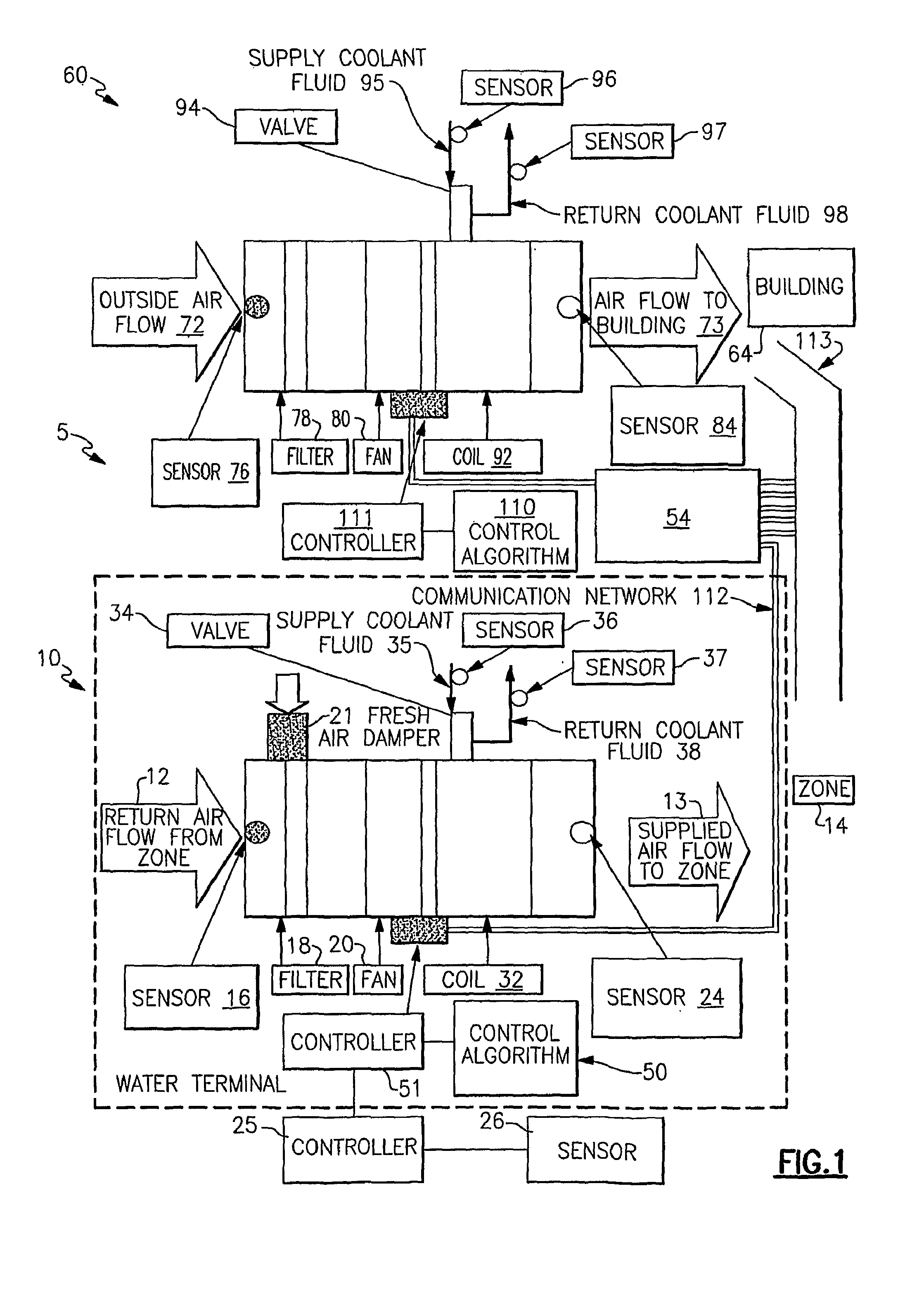
[0022]Referring initially to FIG. 1, there is illustrated a diagrammatical depiction of a building air-conditioning system generally referenced at 5, for conditioning the air of a building 64, wherein the air handling unit generally referenced at 60, the exemplary water terminal generally referenced at 10, equipped with a fresh air damper 21, the building air-conditioning system communication network 112, and the building fresh air duct network 113, comprise the major components of the system.

[0023]The air handling unit 60, is illustrated with a direction of outside air flow 72, coming into it from outdoors, and a direction of air exiting the air handling unit 60, as air flow 73, to the building 64. Outside air flow 72, entering the air handling unit 60, passes over an outside air temperature sensor 76, then through an air handling unit filter 78, at least one air handling unit fan 80, an air handling unit temperature adjusting coil 92, and finally over an air handling unit supply a...


PUM


Abstract

A building air conditioning system control scheme to optimize water terminal capacity and create energy savings by utilizing a building management system signal to run in a mode that maximizes the conditions of the outside air to condition their local zones and potentially require no thermal pre-treatment of outside air by an air handling unit.

Description

CROSS REFERENCE TO RELATED APPLICATIONS[0001]This application is related to another patent application identified by Attorney docket number 210-1050PCT. Both are subject to assignment to Carrier Corporation and each is being filed on an even date herewith.FIELD OF THE INVENTION[0002]The present invention is related to air-conditioning systems, and more particularly to an algorithm to optimize the free cooling mode related to controllers and systems driving hydronic products such as water terminals and, air handling units.BACKGROUND OF THE INVENTION[0003]Usually, commercial building hydronic air-conditioning systems are made of one or more chillers or heat pumps that produce cooling and / or heating water, several water terminals, also referred to as fan coil units, and one or more air handling units that supply fresh air to the building through a duct network in order to maintain a minimum Indoor Air Quality (IAQ) for the comfort of building occupants. Some of these air handlers are e...

Claims


Application Information

Patent Timeline
IPC IPC(8): G05D23/19
CPCF24F11/0009F24F11/0012F24F11/0079Y02B30/78F24F2011/0026Y02B30/542Y02B30/746F24F2011/0006F24F11/30F24F2110/10F24F2110/70F24F11/77Y02B30/54Y02B30/70F24F11/81F24F11/84F24F2120/00F24F11/46F24F11/63
Inventor JOSSERAND, OLIVIERROYET, ERICGOUX, JEANPHILIPPERENAULT, PATRICK
Owner CARRIER CORP
Why Eureka
Eureka Blog
Learn More