Fuel injection device

a fuel injection device and internal combustion engine technology, applied in special fuel injection apparatuses, machines/engines, process and machine control, etc., can solve the problems of reducing output power, reducing fuel flow amount, exhaust degrading, etc., and achieve reducing fuel mileage, reducing atomization, or the like

Inactive Publication Date: 2010-03-18
TOYOTA JIDOSHA KK
View PDF1 Cites 20 Cited by
  • Summary
  • Abstract
  • Description
  • Claims
  • Application Information

AI Technical Summary

Benefits of technology

[0011]As described above, according the aspect of the present invention, the fuel injection valve has the first nozzle hole and the second nozzle hole that are controlled independently of each other to inject fuel. The deposit removal fuel injection is performed in accordance with the deposit amount in the first nozzle hole and the second nozzle hole. As a result, deposits in both the first nozzle hole and the second nozzle hole are removed. Accordingly, the reduction in atomization at the time of fuel injection, reduction in fuel mileage, or the like is reduced.

Problems solved by technology

As a result, the fuel flow amount decreases, the exhaust is degraded, and output power decreases.

Method used


Image

  • Fuel injection device
  • Fuel injection device
  • Fuel injection device

Examples


Embodiment Construction

[0033]Hereinafter, embodiments of the present invention are described in detail with reference to the drawings.

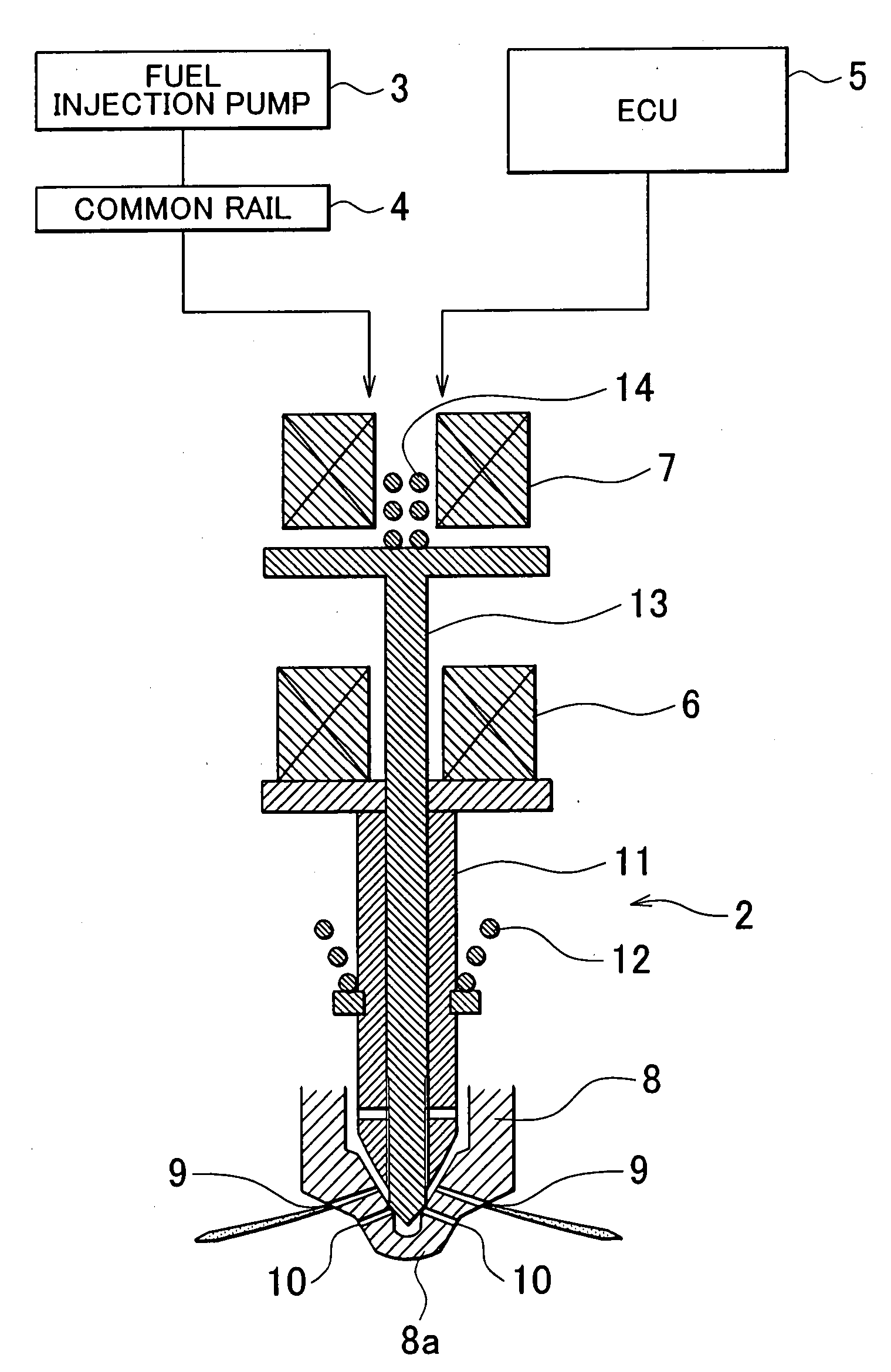
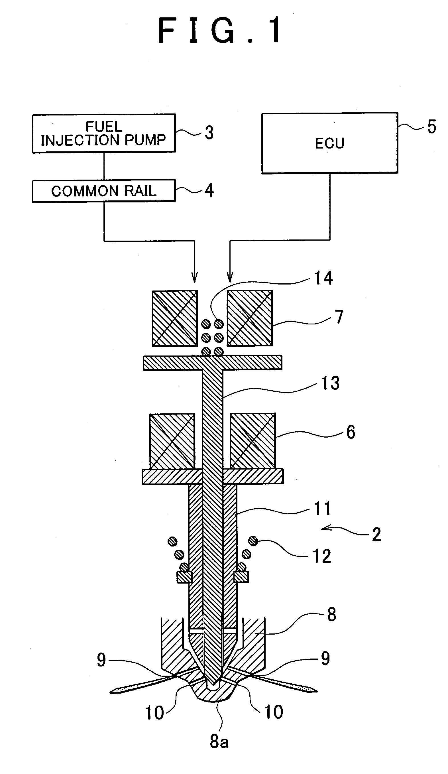
[0034]FIG. 1 is a schematic view illustrating a fuel injection device 1 according an embodiment of the present invention. The fuel injection device 1 includes a fuel injection valve 2, the distal end of which is seen in enlarged cross-section shown in FIG. 1. The fuel injection valve 2 is attached to each cylinder of an unshown engine, and injects fuel into a combustion chamber of the engine. A fuel pressurized by a fuel injection pump 3 is supplied to the fuel injection valve 2 via a common rail 4.

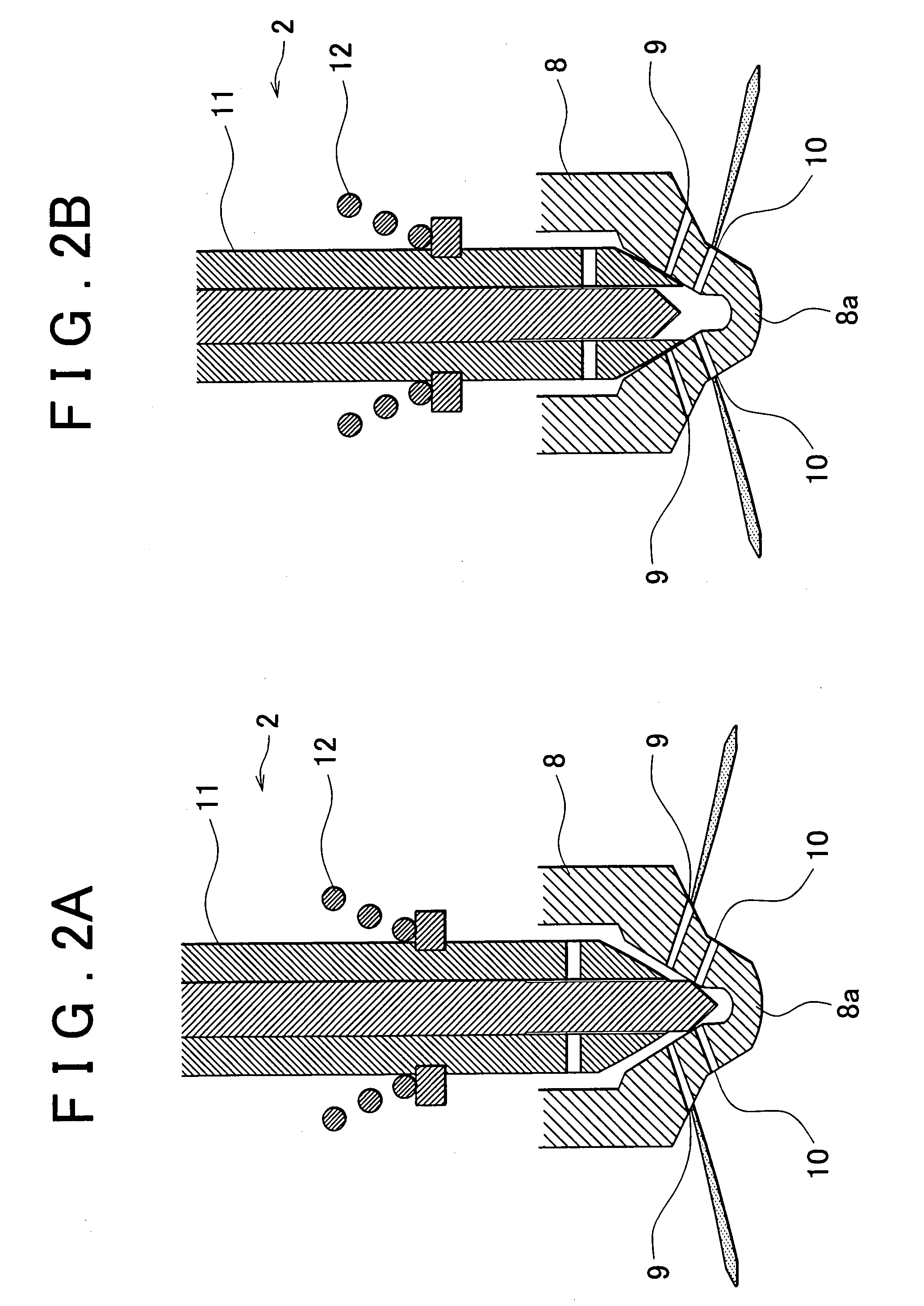
[0035]The fuel injection valve 2 is provided with nozzle holes that are located at a distal end 8a of a nozzle body 8 and are spaced from each other in the fuel flow direction. In other words, the fuel injection valve 2 has a first nozzle hole 9 on the upstream side and a second nozzle hole 10 on the downstream side. The diameter of the second nozzle hole 10 is greater than the d...


PUM


Abstract

A fuel injection device (1) includes a fuel injection valve (2) that injects fuel, and is provided with a first nozzle hole (9) and the second nozzle hole (10), which are controlled independently of each other to inject the fuel. The fuel injection device further includes a controller (5) that performs a deposit removal fuel injection in accordance with an amount of deposits accumulated in the first nozzle hole and/or the second nozzle hole. The deposit removal fuel injection injects fuel to remove the deposits.

Description

BACKGROUND OF THE INVENTION[0001]1. Field of the Invention[0002]The invention relates to a fuel injection device of an internal combustion engine.[0003]2. Description of the Related Art[0004]In a fuel injection valve having a first nozzle hole and a second nozzle hole, that injects a fuel directly into a cylinder, generally, one of the nozzle holes is selected to inject the fuel based on the engine operation state or fuel injection amount. Thus, one of the first nozzle hole and the second nozzle hole is not sometimes used. When the fuel is injected through the first nozzle hole, not the second nozzle hole, deposits are likely to accumulate in the second nozzle hole. In order to prevent the second nozzle hole from being clogged with deposits, Japanese Patent Application Publication No. 2002-310042 (JP-A-2002-310042) describes that, when such a fuel injection (through only the first nozzle hole) continues for a predetermined period, the fuel injection is forcibly performed through the...

Claims


Application Information

Patent Timeline
Patent Type & Authority Applications(United States)
IPC IPC(8): F02D41/40F02M45/02F02M45/08
CPCF02D41/221F02D41/402F02M45/02F02M47/027F02M65/008F02M2200/06F02M2200/46F02M45/086
Inventor FUTONAGANE, YOSHINORIOKUMURA, FUMIHIRO
Owner TOYOTA JIDOSHA KK
Why Eureka
Try Eureka