Air compressor including a disk oil slinger assembly

a technology of air compressor and oil slinger, which is applied in the direction of positive displacement liquid engines, pumps, machines/engines, etc., can solve the problems of reducing the positive benefits of lubrication and oil cooling, reducing and compromising the design of designers, so as to reduce the atomization of oil. , the effect of increasing the flow rate of lubricating and cooling oil

Inactive Publication Date: 2006-05-18
BLACK & DECKER INC
View PDF14 Cites 4 Cited by
  • Summary
  • Abstract
  • Description
  • Claims
  • Application Information

AI Technical Summary

Benefits of technology

[0006] Accordingly, the present invention is directed to a “splash” lubrication system having an oil slinger capable of providing an increased flow rate of lubricating and cooling oil to lubricated components of an air compressor compared to conventional dip stick oil slingers, while reducing oil atomization and oil loss through the crankcase vent. In embodiments of the invention, the oil slinger is comprised of a disk coupled to the crankshaft assembly of the air compressor being lubricated, so that rotation of the crankshaft assembly rotates the disk for splashing lubricating oil from the crankcase's oil sump onto components of the air compressor. Preferably, at least a portion of the oil slinger is continuously submerged in the lubricating oil contained in the oil sump as it is rotated by the crankshaft assembly, thereby decreasing atomization of oil from the oil sump. Further, the oil slinger may be designed to remain at least partially submerged in the oil sump even if the crankcase is tilted providing increased tolerance of operation on non-level surfaces.

Problems solved by technology

A higher velocity or larger profile dip stick will improve lubrication and oil cooling but will increase oil atomization and oil loss through the crankcase vent.
These conflicting phenomena require designers to compromise their design by reducing the positive benefits of lubrication and oil cooling in order to reduce the negative effects of oil loss.
Another problem with such traditional splash oil lubrication systems is that a number of the air compressors in which such systems are used are portable and are regularly moved by hand from one work site to another.
If such portable air compressors are not properly leveled prior to operation, the dip stick splash lubricator may not reach the oil sump causing a lack of needed lubrication and cooling, possibly leading to subsequent component failure.

Method used


Image

  • Air compressor including a disk oil slinger assembly
  • Air compressor including a disk oil slinger assembly
  • Air compressor including a disk oil slinger assembly

Examples


Embodiment Construction

[0022] Reference will now be made in detail to the presently preferred embodiments of the invention, examples of which are illustrated in the accompanying drawings.

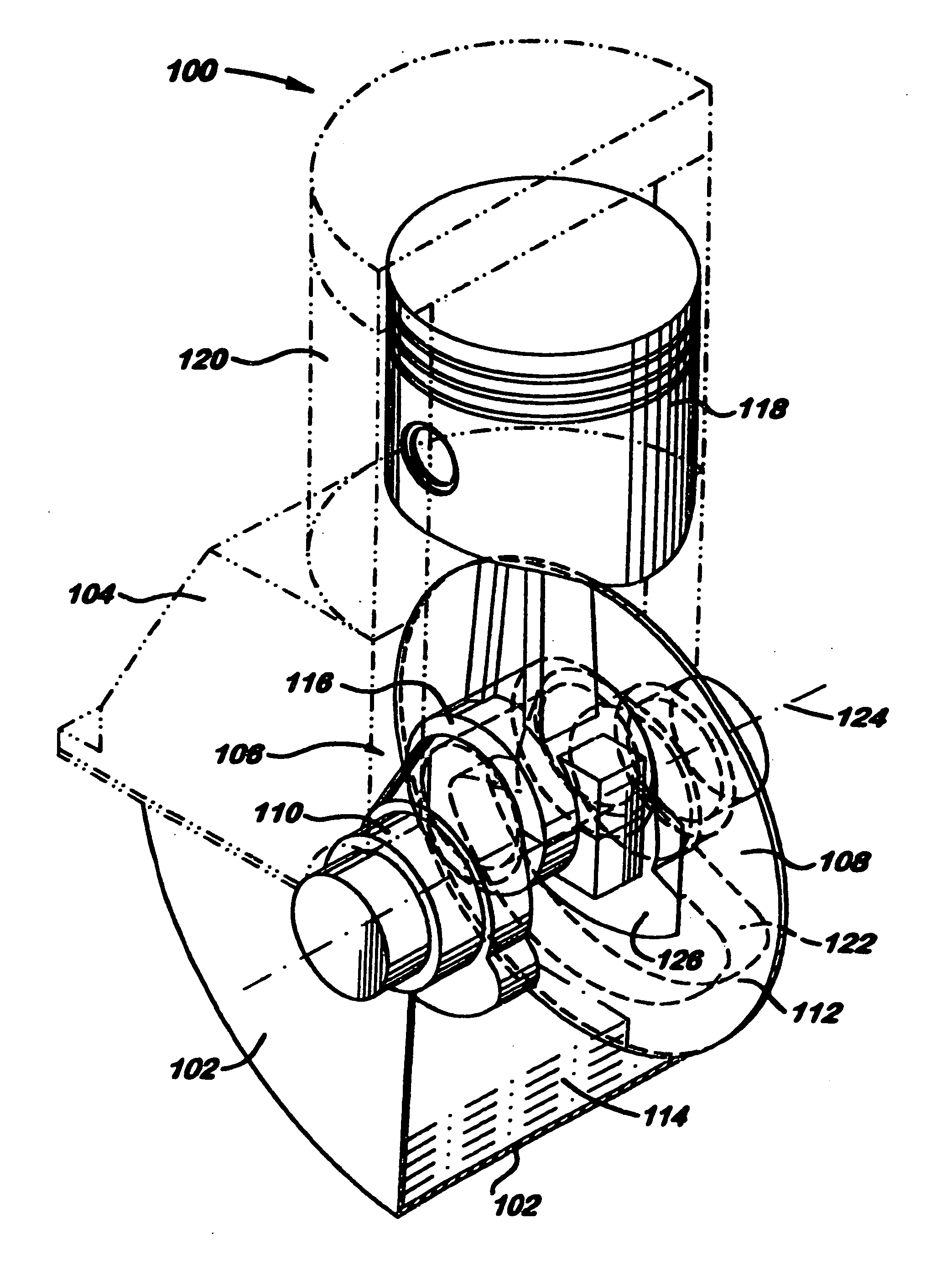
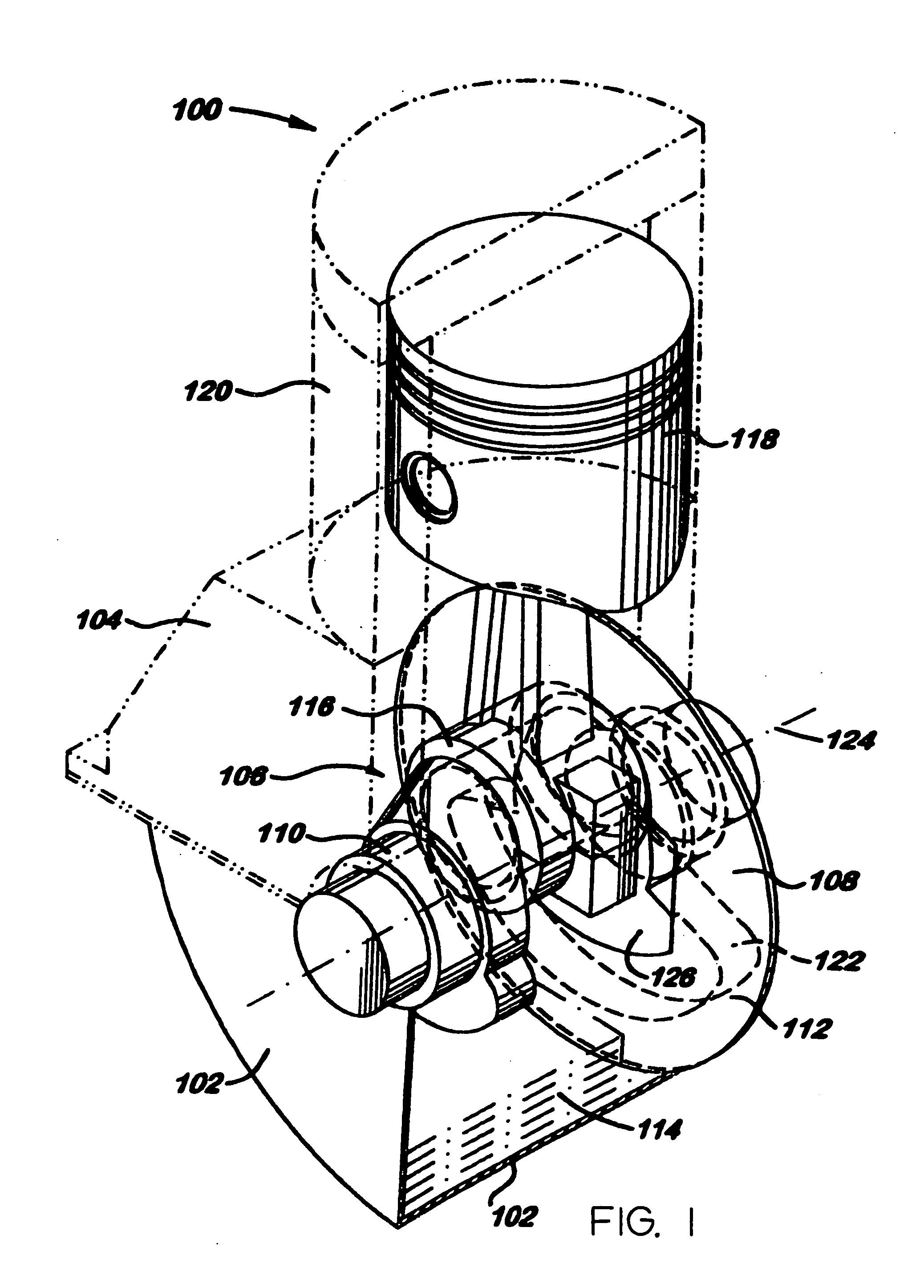
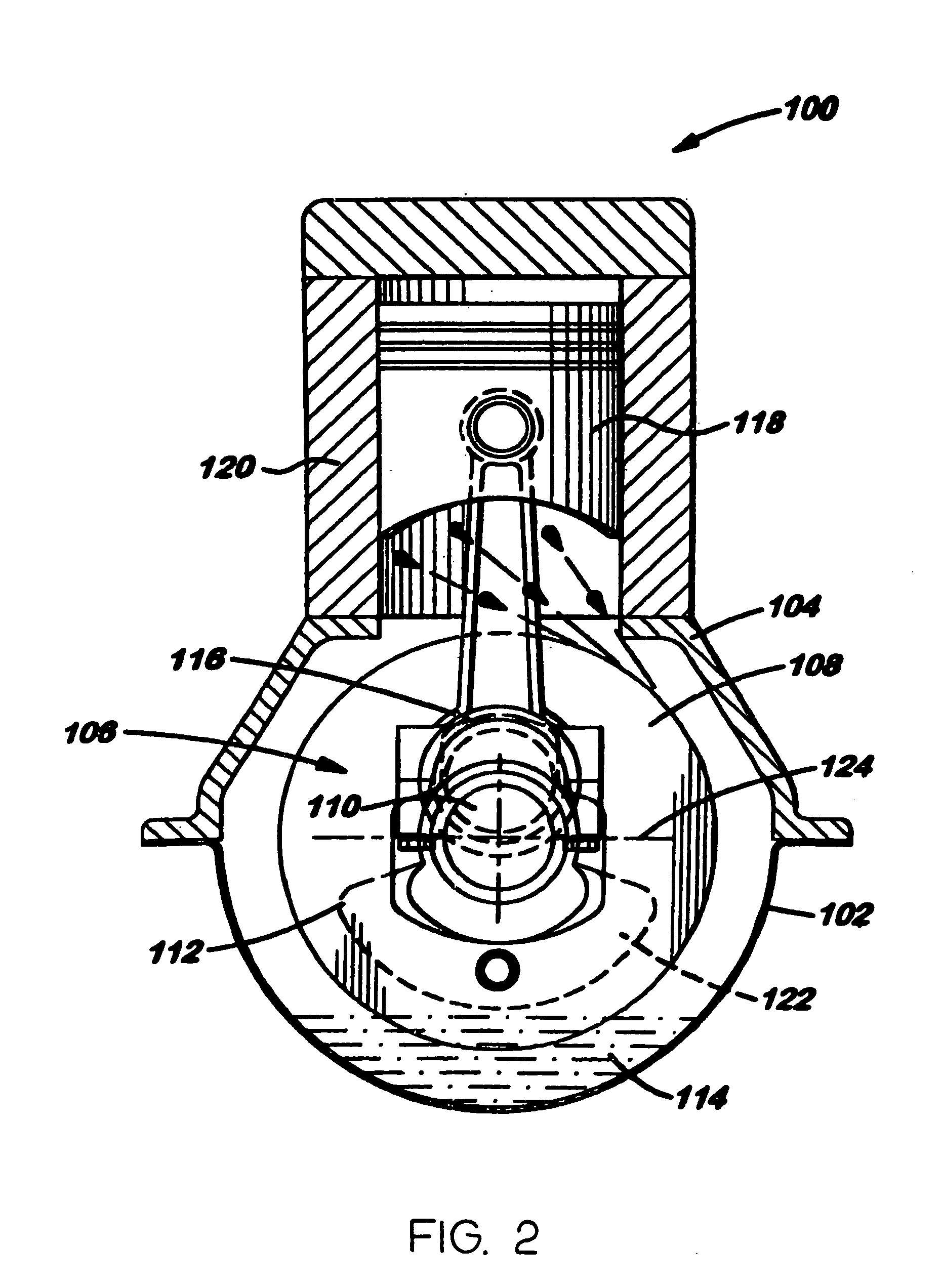
[0023] Referring now to FIGS. 1, 2, 3 and 4, an exemplary “splash” lubrication system suitable for providing lubrication to the moving components of an air compressor in accordance with the present invention is described. The lubrication system 100 includes an oil sump 102 formed in the crankcase 104 of the air compressor 106 in which the lubrication system 100 is employed and an oil slinger 108 coupled to the air compressor's crankshaft assembly 110.

[0024] In one embodiment, the oil slinger 108 is comprised of a continuous disk 112 attached to the crankshaft assembly 110. Rotation of the crankshaft assembly 110 rotates the disk for splashing lubricating oil 114 from the oil sump 102 onto components of the air compressor 106 being lubricated (e.g., crankshaft assembly 110, journal 116, piston 118, cylinder wall 120, and...


PUM


Abstract

A “splash” lubrication system having an oil slinger capable of providing an increased flow rate of lubricating and cooling oil to lubricated components of the system compared to conventional dip stick oil slingers while reducing oil atomization and oil loss through the crankcase vent is disclosed. In embodiments of the invention, the oil slinger is comprised of a disk coupled to the crankshaft assembly of a direct drive oil-lube air compressor. The air compressor includes a universal electric motor which drives the crankshaft assembly, thereby causing the crankshaft assembly to rotate, which in turn, rotates the disk for splashing lubricating oil from the crankcase's oil sump onto the moving parts of the air compressor being lubricated by the lubricating system.

Description

CROSS-REFERENCE TO RELATED APPLICATIONS [0001] The present application is a continuation-in-part of U.S. patent application Ser. No. 10 / 118,675 filed Apr. 9, 2002, which is a continuation-in-part of U.S. patent application Ser. No. 09 / 861,285 filed May 18, 2001. U.S. patent application Ser. No. 10 / 118,675 and U.S. patent application Ser. No. 09 / 861,285 are herein incorporated by reference in their entireties.FIELD OF THE INVENTION [0002] The present invention generally relates to the field of oil lubrication devices for air compressors, and more particularly to an air compressor including a disk oil slinger suitable for use in oil lubricated air compressors. BACKGROUND OF THE INVENTION [0003] Typically, lower cost oil lubricated air compressors have employed a “splash” lubrication system to distribute oil from the oil sump to the mechanical bearings, seals, valves, pistons and other parts that require lubrication and oil cooling. A small protruding piece of material or “dip stick” i...

Claims


Application Information

Patent Timeline
Patent Type & Authority Applications(United States)
IPC IPC(8): F04B35/04F04B17/00F01M9/06F16N7/26
CPCF01M9/06F04B39/0094F04B39/0223F04B39/0284F04B41/02F16N7/26
Inventor BURKHOLDER, ROBERT F.
Owner BLACK & DECKER INC
Why Eureka
Try Eureka