
Watertube and method of making and assembling same within a boiler or heat exchanger

a technology of water pipes and water pipes, which is applied in the direction of fluid heaters, indirect heat exchangers, lighting and heating apparatus, etc., can solve the problems of eliminating the fillet weld and further complicating the already difficult and inefficient process

Inactive Publication Date: 2010-03-25
BURNHAM SERVICES
View PDF27 Cites 8 Cited by
  • Summary
  • Abstract
  • Description
  • Claims
  • Application Information

AI Technical Summary

Benefits of technology

[0012]According to a first aspect of the present invention, a watertube for use to conduct water or steam is provided. The watertube has an intermediate portion with a first end portion and a second end portion. The first end portion has an integrally formed radially outward extending, circumferential flange which is spaced from a free end of the first end portion. The flange is formed to accept a driving force applied in a direction parallel to the longitudinal axis of the first end portion toward the free end of the first end portion without failing. A radially extending surface on a distal side of the flange is provided. The radially extending surface is dimensioned to engage an apparatus which exerts the driving force thereon. The first end portion has a tapered outer wall which tapers down from the flange to the free end of the first end portion. The application of an axial force to the radially extending surface of the flange results in the tapered first end portion being received in an opening of a manifold and secured in fluid-tight engagement therein.
[0015]According to yet another aspect of the present invention, a boiler or heat exchanger is provided. The boiler or heat exchanger has at least a pair of opposed domes, manifolds, or like castings and one or more metallic watertubes each having opposite ends connected to the opposed domes, manifolds, or like castings. At least one end section of the one-piece watertube is formed to have an integral outwardly-extending circumferential flange. The flange provides a readily-engagable, radially-extending surface on which a substantially axially-directed force can be applied to drive the end of the tube into sealing engagement with a hole, port, or socket of one of the domes, manifolds, or like castings. Preferably, a portion of the tube extending from the circumferential flange to an adjacent end face of the tube is formed with an inward taper such that a diameter of an outer wall of the tube progressively decreases from the circumferential flange to the end face. A wall defining the hole, port, or socket in the dome, manifold or like casting can be tapered to enable tight engagement with the tapered end of the tube. The watertube can have a substantially serpentine shape between its opposite ends.
[0016]According to yet another aspect of the present invention, a boiler is provided that has an elongate base header located adjacent a base of the boiler, an elongate dome header located at the top of the boiler, and a plurality of separate watertubes each having an intermediate section and opposite end sections. An upper one of the end sections of each watertube is connected to the dome header and a lower one of the end sections of each watertube is connected to the base header such that the intermediate section extends through a combustion chamber of the boiler. The intermediate section of each watertube has a substantially constant outer diameter along its full length and is closely spaced to adjacent watertubes within the combustion chamber. At least one of the end sections of each watertube has a transition that reduces the diameter of the watertube as it extends from the intermediate section and transitions to a reduced-diameter free end tip of the end section.

Problems solved by technology

A problem with the use of the fillet weld is that the fillet weld eliminates any clean or flat surface of the circumferential flange on which a force can be readily applied to drive the tube end into the hole in a dome or the like.
Existence of the fillet weld further complicates the already difficult and inefficient process of handling relatively heavy tubes within small spaces available during a boiler or heat exchanger assembly and the process of driving the tube ends into position within the boiler in a manner that provides leak-free connections.

Method used


Image

  • Watertube and method of making and assembling same within a boiler or heat exchanger
  • Watertube and method of making and assembling same within a boiler or heat exchanger
  • Watertube and method of making and assembling same within a boiler or heat exchanger

Examples


Embodiment Construction

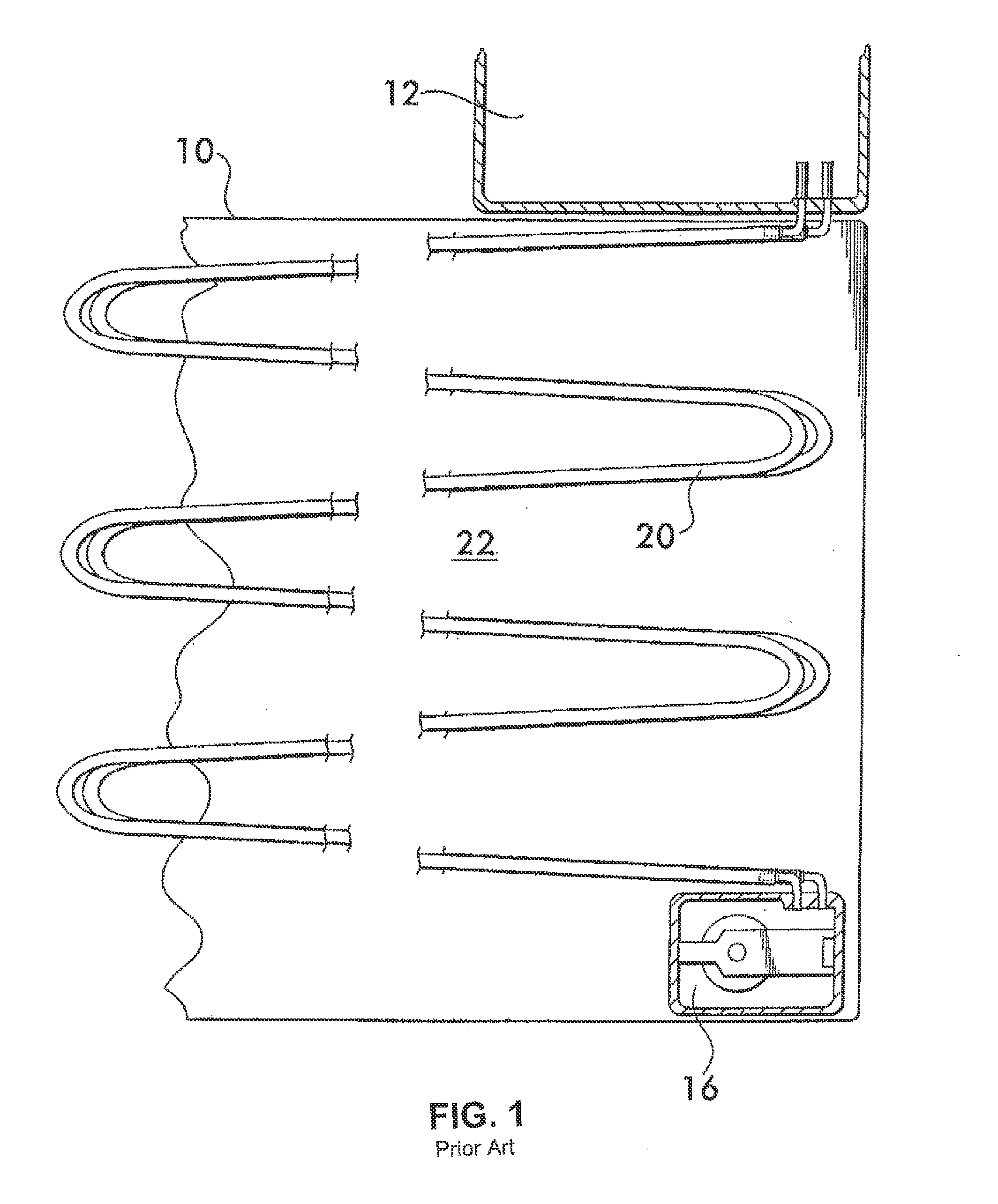
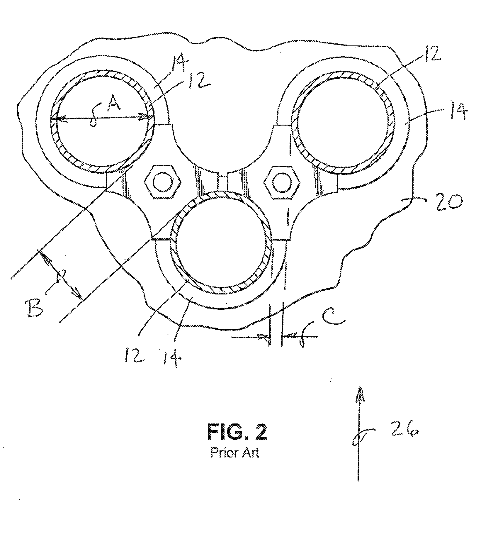
[0039]The present invention relates to watertubes that are used in commercial boilers, heat exchangers, and like apparatus. FIG. 1 illustrates an example of a watertube boiler 10 that is known in the art. The boiler 10 includes at least one upper dome 12 and at least one base header 16. The so-called bent watertubes 20 have opposite ends interconnecting the base header 16 to the dome 12. A serpentine portion of each watertube 20 extends within a combustion chamber 22 of the boiler. System water is fed into the boiler 10 or dome 12 and travels within the watertubes 20. The water is heated in the watertubes 20 and the heated water or steam flows from the watertubes 20 into the dome 12 and then to a system supply pipe.

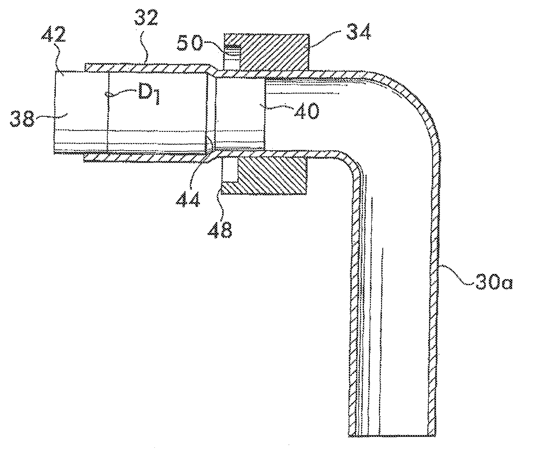
[0040]A typical watertube is made of a metallic material. The inner and outer diameters of such a watertube are typically constant from end-to-end. For example, the outer diameter of each tube may be 1.5 inch, and the inner diameter of each tube may be 1.25 inch thereby p...


PUM

PropertyMeasurementUnit
Lengthaaaaaaaaaa
Diameteraaaaaaaaaa
Distanceaaaaaaaaaa

Abstract

A one-piece tube for use as a watertube within a watertube boiler or heat exchanger has a free end section that is formed to have an integral, outward-extending circumferential ring, or flange, a spaced distance from an adjacent end face of the tube. A boiler is provided that has an elongate header and a plurality of separate watertubes each having an intermediate section and opposite end sections. An end section of each watertube is connected to the header. The intermediate section of each watertube has a substantially constant outer diameter along its full length and is closely spaced to adjacent watertubes within the combustion chamber. At least one of the end sections of each watertube has a transition that reduces the diameter of the watertube as it extends from the intermediate section to an outwardly-extending circumferential flange. This arrangement permits close spacing of the connection sites of the watertubes to the header and permits the connection sites to be provided in a linear array.

Description

CROSS-REFERENCE TO RELATED APPLICATIONS[0001]This Application is a continuation-in-part application of U.S. Utility application No. Ser. 11 / 380,456, filed Apr. 27, 2006, and entitled “Watertube and Method of Making and Assembling same within a Boiler or Heat Exchanger.”FIELD OF THE INVENTION[0002]The present invention relates to a boiler and / or heat exchanger used in a domestic and / or commercial heating and / or hot water and / or steam system, and more specifically, the present invention relates to a watertube structure and to methods of making a watertube and assembling it within a boiler and / or similar heat exchanger. The invention also relates to a watertube, a header and watertube assembly, a boiler having the header and watertube assembly, and a method of assembling the boiler.BACKGROUND OF THE INVENTION[0003]Examples of boilers having watertubes are provided by U.S. Pat. No. 1,824,256 issued to Bryan and U.S. Pat. No. 4,993,368 issued to Jones et al. For example, the Bryan patent...

Claims


Application Information

Patent Timeline
IPC IPC(8): F22B37/10
CPCB21D41/04F24H1/40F28F9/12F28D7/08F28D7/082F28D1/0477
Inventor MOORE, THOMAS WAYNEBENDER, EDWARD A.
Owner BURNHAM SERVICES
Learn More