Active Thermal Protection For Fuel Injectors

a fuel injector and active thermal protection technology, which is applied in the direction of efficient propulsion technologies, machines/engines, lighting and heating apparatus, etc., can solve the problems of reducing the quality of fuel, reducing the service life of fuel nozzles, and weakening the structural strength

Active Publication Date: 2010-03-25
WOODWARD GOVERNOR CO
View PDF24 Cites 35 Cited by
  • Summary
  • Abstract
  • Description
  • Claims
  • Application Information

AI Technical Summary

Benefits of technology

[0009]Embodiments of the present invention provide improved fuel injectors and turbine engines. In one embodiment, an improved fuel injector including an active cooling system is provided. Further yet, in an embodiment, an improved fuel injector including an active cooling system that siphons air from a compressor discharge area of a turbine through a cooling passage that cools the air and then passes it through the fuel injector is provided. Still further yet, an improved turbine engine that includes a cooling system that includes a cooling passage that has an inlet within a compressor discharge area and an outlet in a combustor as well as portion in thermal communication with the fuel injector is provided.

Problems solved by technology

More particularly, if too much heat is transferred to the fuel, the fuel can begin to coke, thereby ruining or reducing the quality of the fuel.
Further, coking of the fuel can cause coke depositions in the fuel injector negatively effecting the fuel flow from the injector.
The high heat also weakens the structural strength and exacerbates corrosion of the fuel nozzle.
Unfortunately, however, due to technology advances, thereby ever-increasing the harsh environment downstream of the compressor, the fuel injector is being exposed to and required to withstand higher environment temperatures, sometimes in excess of 1600 degrees Fahrenheit.
Further, complicating the issue is the fact that fuel is being used more extensively as a heat sink or cooling agent for various systems, particularly in aircrafts, prior to consumption of the fuel.
Excessive temperature also weakens the strength and accelerates corrosion of the metal structures of the fuel nozzle.
Due to these increases in temperature and sources of heat energy, standard heat shield / stagnant air arrangements are becoming less effective in preventing deleterious effects on the fuel.

Method used


Image

  • Active Thermal Protection For Fuel Injectors
  • Active Thermal Protection For Fuel Injectors
  • Active Thermal Protection For Fuel Injectors

Examples


Embodiment Construction

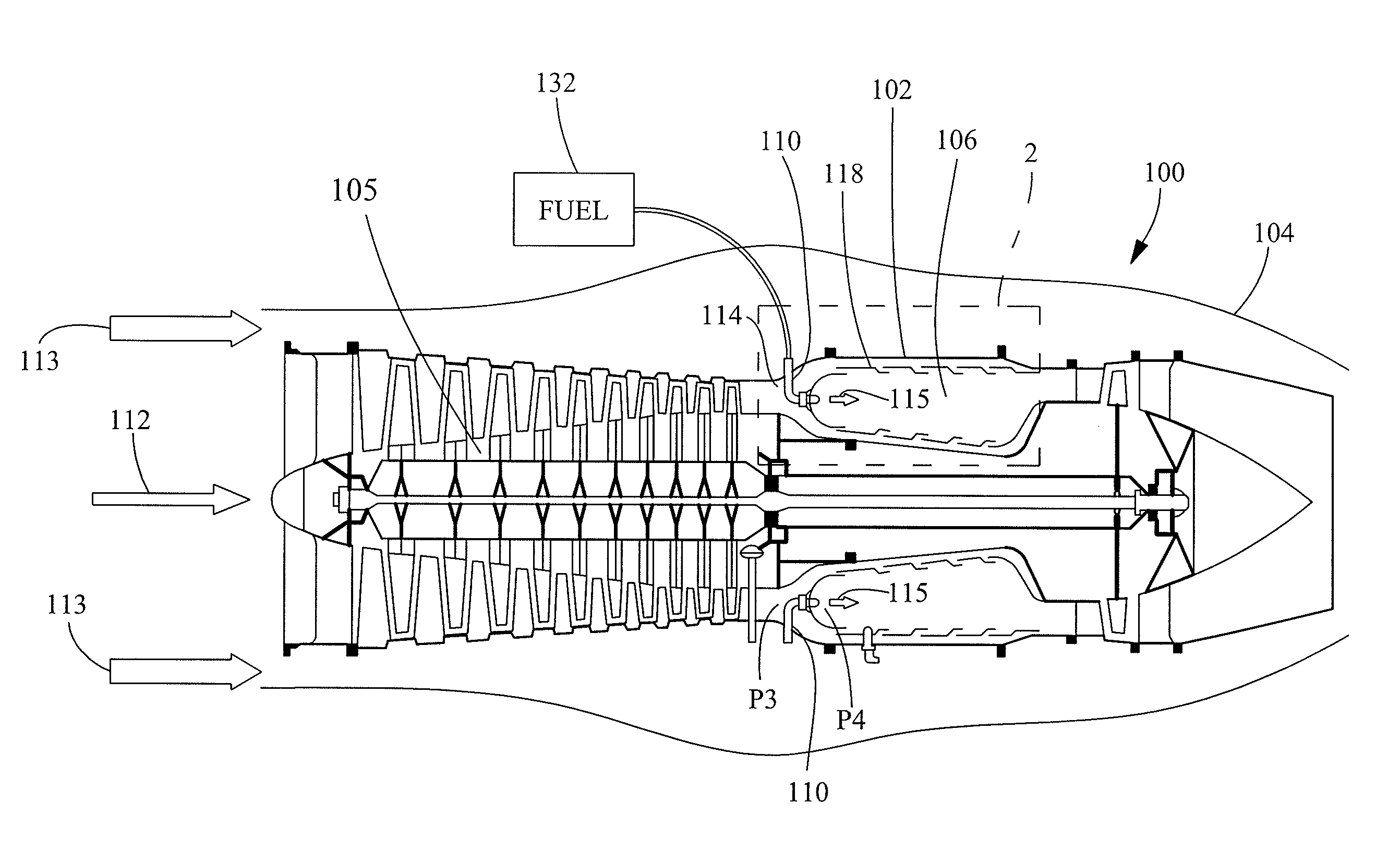
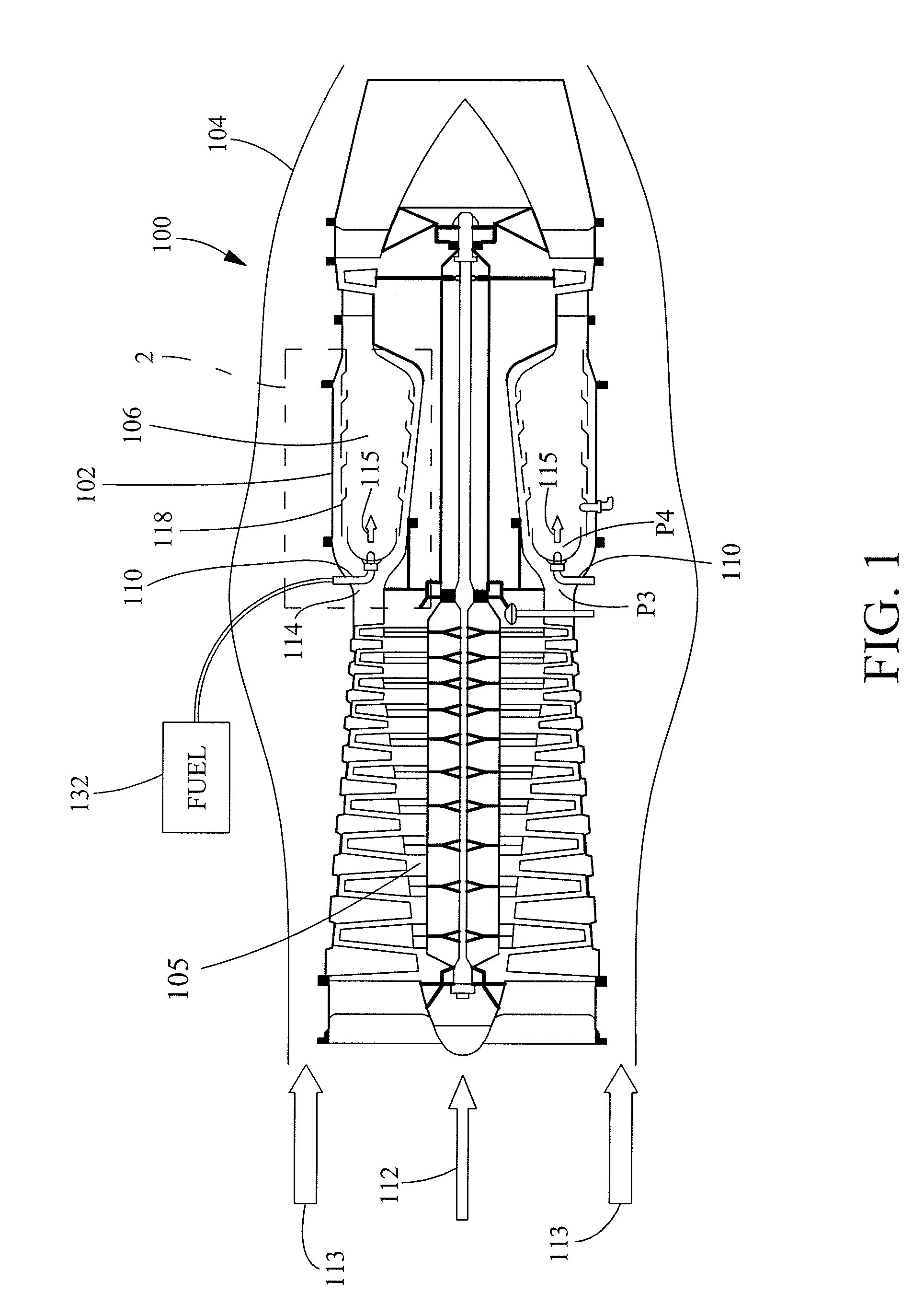
[0019]Turning now to FIG. 1, a simplified illustration of a turbine engine 100 according to the teachings of the present invention is illustrated. The turbine engine 100 includes, among other things, an engine case 102 housed within a nacelle 104, i.e. a shroud surrounding the engine case 102, and other components that cause the turbine engine 100 to operate. Within the engine case 102, the turbine engine 100 includes a compressor 105, a combustor 106 or combustion chamber and a plurality of fuel injectors 110 (also referred to or known as fuel nozzles).

[0020]Atmospheric air, illustrated as arrow 112 enters compressor 105 and is compressed such that it exits into compressor discharge area 114 upstream of combustor 106. The compressed air within the compressor discharge area 114 is high-pressure and high temperature. The pressure of the compressor discharge area 114 will be referred to herein as pressure P3.

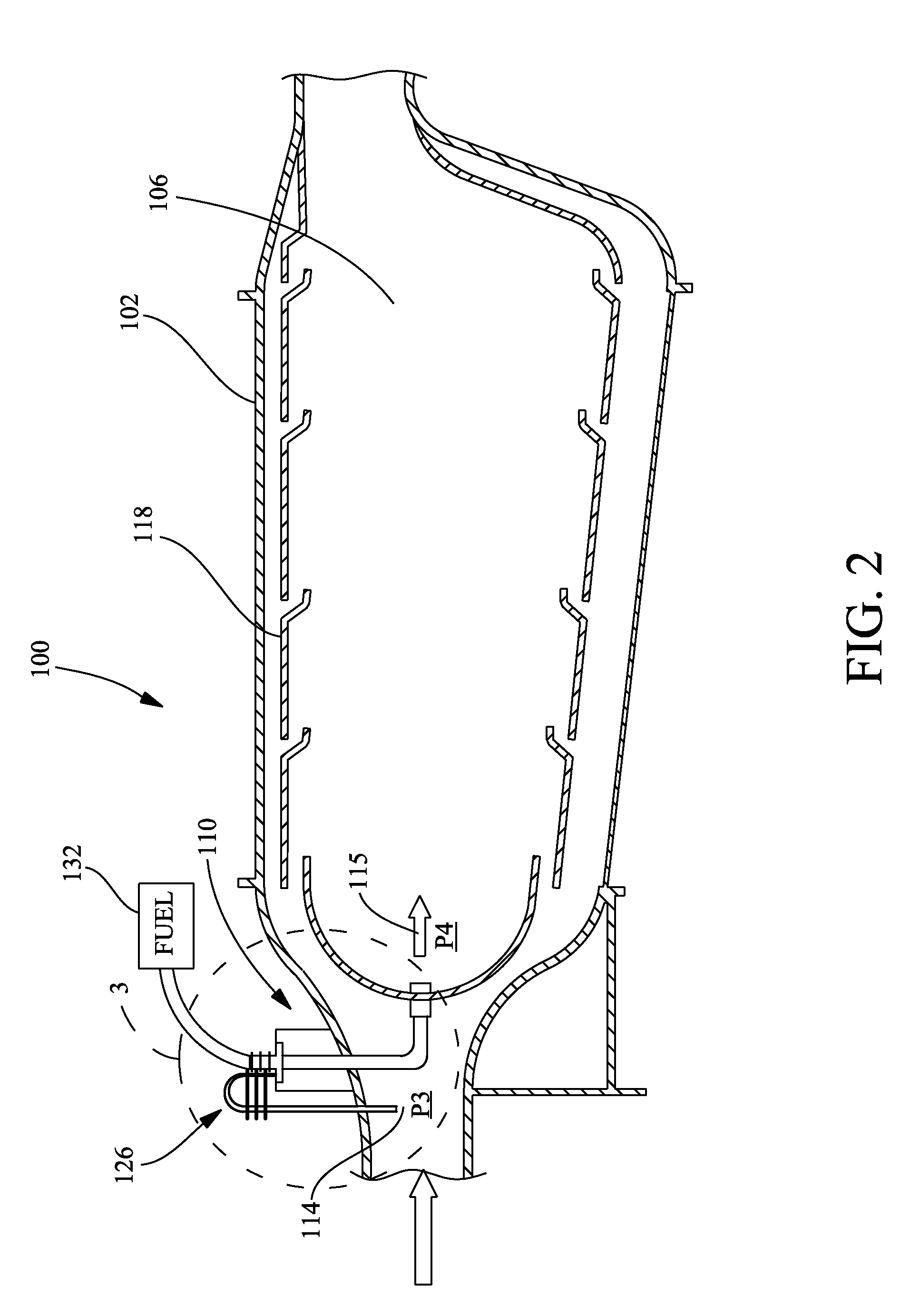
[0021]Downstream from the compressor discharge area 114 is the combustor 106 ...


PUM


Abstract

A fuel injector and turbine engine incorporating the fuel injector are provided. The fuel injector includes an active cooling system that insulates fuel flowing through the fuel injector from heat energy within the turbine engine. The cooling system includes a cooling air passage that includes an inlet and an outlet. The inlet and outlet are in fluid communication with the interior of an engine case of the turbine engine. The inlet is at a higher air pressure location than the outlet such that air is siphoned through the cooling air passage. A portion of the cooling air passage includes a heat exchanger for extracting heat energy from the cooling air. The cooling air passes through the fuel injector after it has passed through the heat exchanger. The heat exchanger is positioned external to the engine case and in thermal communication with the ambient.

Description

FIELD OF THE INVENTION[0001]This invention generally relates to fuel delivery systems and more particularly to fuel injectors (i.e. fuel nozzles) for delivering fuel to combustion chambers for combustion engines.BACKGROUND OF THE INVENTION[0002]Fuel injectors (a.k.a. fuel nozzles) are important components of gas turbine engines. Because the fuel injector is the source of the fuel, the fuel injector can provide significant play in the role of engine performance.[0003]Because the fuel injector is positioned, at least partially, within the engine case, a fuel injector includes a support / stem through which an internal fuel tube extends. The fuel tube will be connected to an atomizer or other tip member of the support / stem to improve the delivery state of the fuel so that it will more fully mix with air in the engine case. Typically, the fuel injector is positioned downstream of a compressor unit and upstream from a combustor of the turbine. Typically, the location between the compressor...

Claims


Application Information

Patent Timeline
Patent Type & Authority Applications(United States)
IPC IPC(8): F02M61/14
CPCF02C3/30F02C7/185Y02T50/675F23R3/283F02C7/222Y02T50/60
Inventor HICKS, PAUL G.LEE, FEI PHILIP
Owner WOODWARD GOVERNOR CO
Why Eureka
Try Eureka