Adjustable Over Tube Anti Roll Bar

a technology of anti-roll bar and over-tube, which is applied in the direction of resilient suspension, vehicle spring, interconnection system, etc., can solve the problems of short torsional spring having a greater tendency to over-torsion, and achieve the effects of lightening and strengthening the torque arm, facilitating positioning, and easy adaptation to many different vehicles

Inactive Publication Date: 2010-03-25
CIASULLI ANDREW
View PDF0 Cites 9 Cited by
  • Summary
  • Abstract
  • Description
  • Claims
  • Application Information

AI Technical Summary

Benefits of technology

[0014]One advantage of the present invention is that it allows for a torsion spring longer than the width between the torque arms without the need to bend the torque arms.
[0015]Another advantage of the present invention is the ability for the torque arms to be easily positioned anywhere along the main support tube allowing for easy adaptation to many different vehicles.
[0016]Still another advantage is the ability to move the torque arms along the main support tube, the

Problems solved by technology

If the suspension has a great deal of travel, a relatively short torsional spring will have a greater tendency to over twist with resultant fatigue as it tries to compensate for applied torque force.
While avoiding the aforementioned disadvantage

Method used


Image

  • Adjustable Over Tube Anti Roll Bar
  • Adjustable Over Tube Anti Roll Bar
  • Adjustable Over Tube Anti Roll Bar

Examples


Embodiment Construction

[0027]As required, detailed embodiments of the present invention are disclosed; however, it is to be understood that the disclosed embodiments are merely exemplary of the invention that may be embodied in various forms. The figures are not necessary to scale, and some features may be exaggerated to show details of particular components. Therefore, specific structural and functional details disclosed are not to be interpreted as limiting, but merely as a basis for the claims and as a representative basis for teaching one skilled in the art to variously employ the present invention.

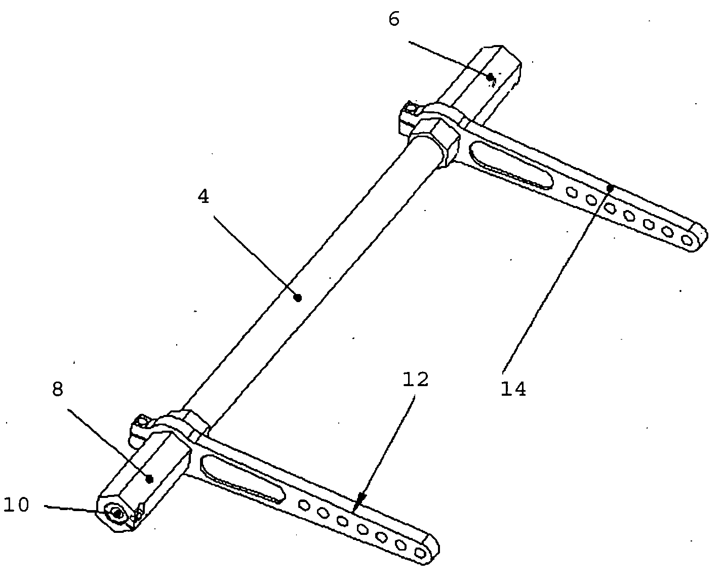
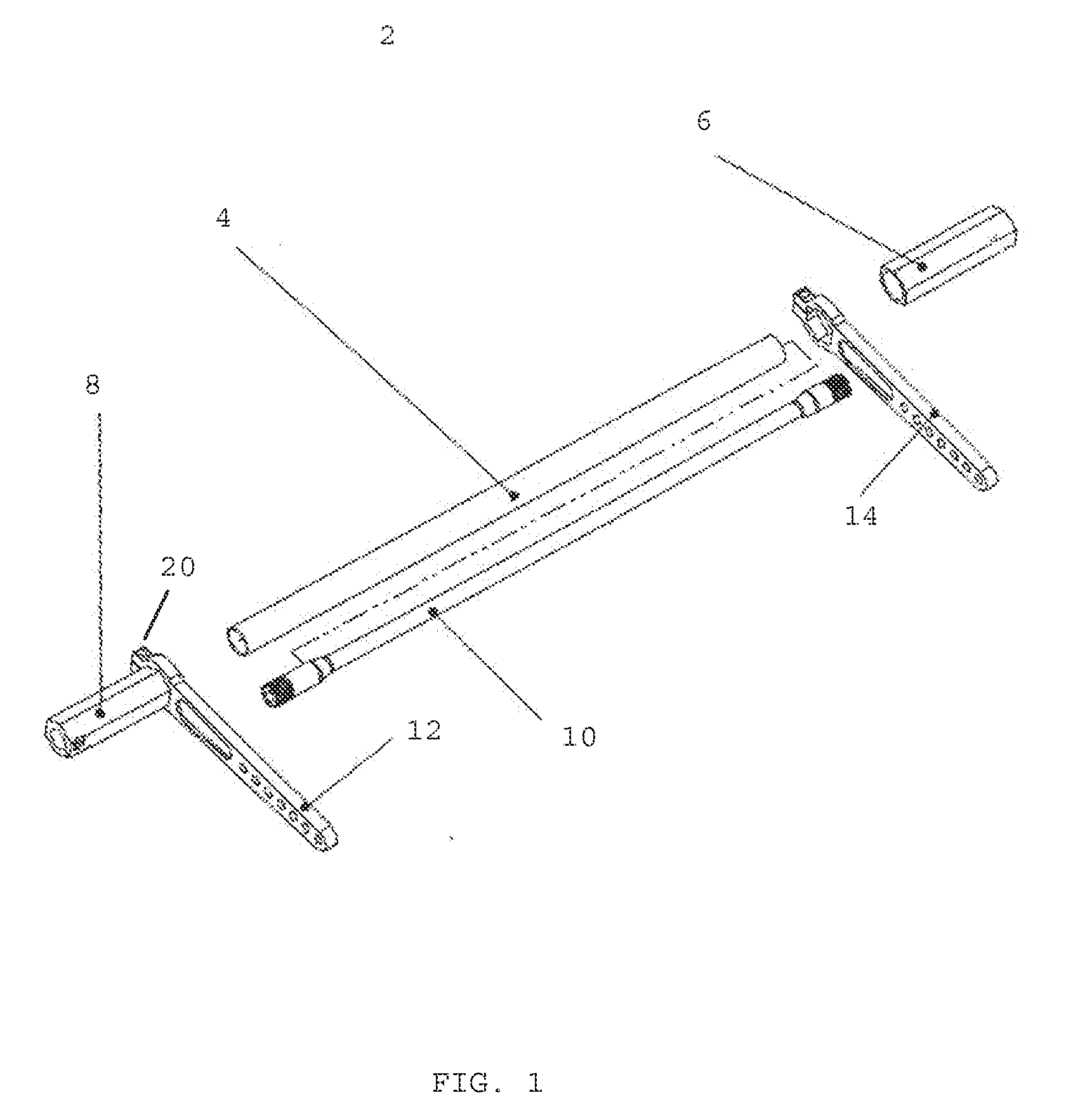
[0028]Referring now to the figures, FIG. 1 is an exploded isometric view depicting the over tube anti-roll bar assembly of the present invention. Anti roll bar assembly 2 is comprised of a main support tube 4, over tubes 6 and 8, torsional spring 10, and torque arms 12 and 14.

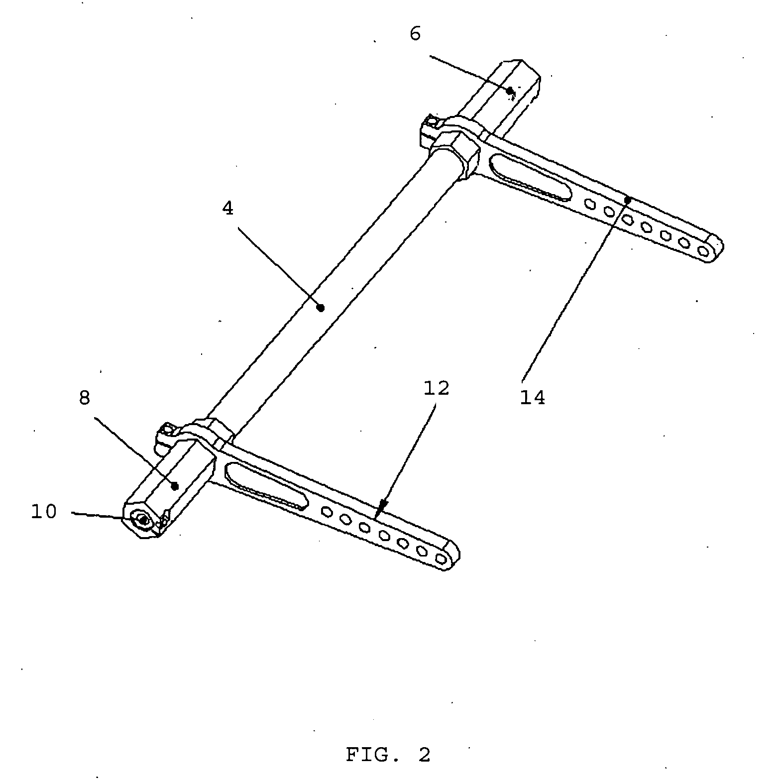
[0029]Turning to FIG. 2, anti roll bar main support tube 4 is fixedly mounted to a vehicle (not shown) at, for example behind the fro...


PUM


Abstract

An anti roll bar assembly is provided having opposing over tubes that are fixed to a torsional spring at both ends. The torsional spring is suspended within a main support tube which also rotatably receives each over tube. Torque arms are fabricated to be positioned along each over tube such that an inter torque arm width is less than a torsional spring length.

Description

CROSS REFERENCE TO RELATED APPLICATIONS[0001]This application claims benefit of U.S. Application No. 61 / 194,111 filed Sep. 24, 2008.FIELD OF THE INVENTION[0002]This invention relates generally to vehicle suspensions, and in particular, to an adjustable over tube anti roll bar.BACKGROUND OF THE INVENTION[0003]As a vehicle enters a turn, the resulting centrifugal forces acting on the vehicle roll the vehicle body about its roll center relative to the underlying suspension system. This centrifugal force also displaces the body laterally and outwardly, causing the vehicle to pivot about the contact of its outer wheels with the road surface.[0004]Anti-roll bars are used to limit this tendency of moving vehicles to roll or lean while traversing a corner. This is achieved by coupling the left suspension members to the right suspension members using a torsional spring so that relative wheel displacement transmits a torque force to the wheel on the opposite side.[0005]The torsional spring is...

Claims


Application Information

Patent Timeline
IPC IPC(8): B60G21/055
CPCB60G21/055B60G2206/427B60G2202/1351B60G2202/135
Inventor CIASULLI, ANDREW
Owner CIASULLI ANDREW
Why Eureka
Try Eureka