Magnetic resonance system with transmission of a digitized magnetic resonance signal across an air gap

a magnetic resonance and air gap technology, applied in the field of magnetic resonance systems, can solve the problems of limited analog signal transmission, inability to reliably use plug connections in practice, and only qualitatively low-grade magnetic resonance signals, etc., and achieve the effect of reliable and comfortabl

Active Publication Date: 2010-03-25
SIEMENS HEALTHCARE GMBH
View PDF9 Cites 10 Cited by
  • Summary
  • Abstract
  • Description
  • Claims
  • Application Information

AI Technical Summary

Benefits of technology

[0009]An object of the present invention is to provide a reliable and comfortable mode of signal tr...

Problems solved by technology

This manner of operation, however, provides only qualitatively low-grade magnetic resonance signals.
This type of transmission, however, is limited to analog signals for reasons of the...

Method used


Image

  • Magnetic resonance system with transmission of a digitized magnetic resonance signal across an air gap
  • Magnetic resonance system with transmission of a digitized magnetic resonance signal across an air gap
  • Magnetic resonance system with transmission of a digitized magnetic resonance signal across an air gap

Examples


Embodiment Construction

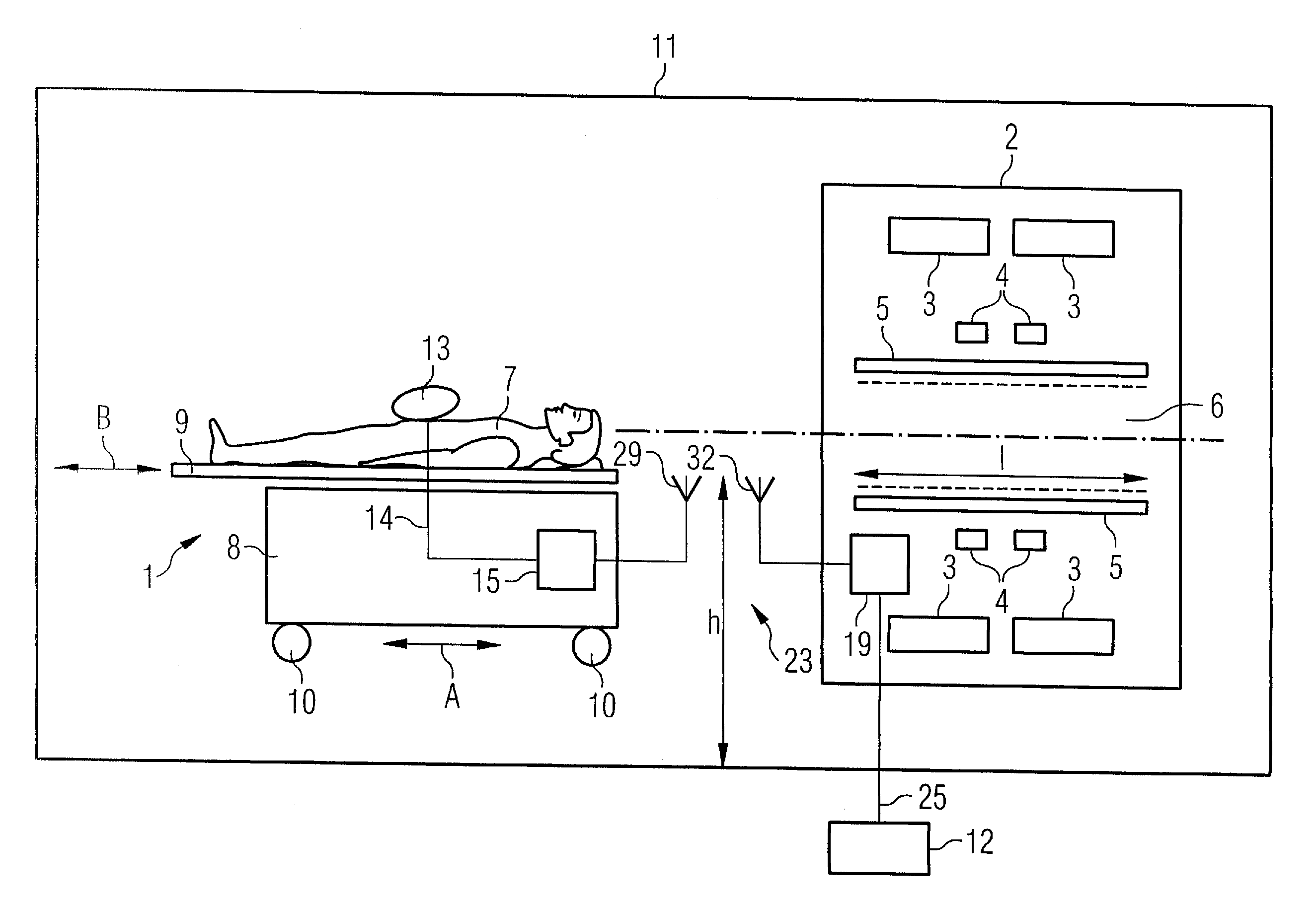
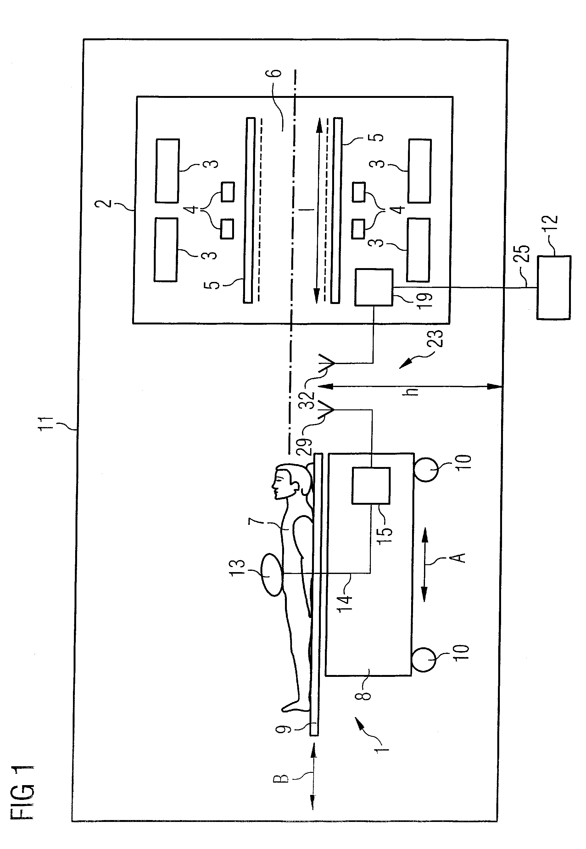
[0024]As shown in FIG. 1, a magnetic resonance system has a patient receptacle 1 and a base body2. The patient receptacle 1 and the base body 2 interact.

[0025]The base body 2 has at least one basic field magnet system 3, one gradient system 4 and an RF transmission coil 5. A static basic magnetic field is generated by the basic field magnet system 3 in a patient tunnel 6 that is stationary relative to the base body 2. The static basic magnetic field can be 1.5 T or 3 T, for example. Other values are also possible depending on the design of the basic field magnet system 3. Gradient fields are generated in the patient tunnel 6 by means of the gradient system 4. The gradient system 4 can be designed as is generally known. RF excitation fields are generated in the patient tunnel 6 by the RF transmission coil 5. The RF transmission coil 5, for example, can be fashioned as a birdcage resonator or as an array antenna.

[0026]The patient tunnel 6 exhibits a length l that is normally between 4...


PUM


Abstract

A magnetic resonance system has a patient receptacle and a base body. The patient receptacle has a subframe and a patient bed supported thereon so as to move a patient thereon through the base body. The base body has a basic field magnet system, a gradient system and an RF system that are operable to obtain an analog magnetic resonance signal from the patient. The patient receptacle has a signal conversion device composed of an A/D converter, a modulator, and a transmitter. The base body has a signal conversion device composed of a receiver and a demodulator. The A/D converter receives the magnetic resonance signal and digitizes it. The modulator modulates a carrier signal with the digitized magnetic resonance signal. The transmitter transmits the modulated carrier signal via an air gap to the receive. The receiver receives the transmitted carrier signal. The demodulator extracts the digitized magnetic resonance signal from the received carrier signal by demodulation and supplies it to an evaluation device for continuing evaluation.

Description

BACKGROUND OF THE INVENTION[0001]1. Field of the Invention[0002]The present invention concerns a magnetic resonance system.[0003]2. Description of the Prior Art[0004]Magnetic resonance systems typically has a patient receptacle in a data acquisition unit (scanner) interacting with the patient in the receptacle. The scanner has at least one basic field magnet system, a gradient system and an RF transmission coil. A static basic magnetic field is generated by the basic field magnet system in a patient tunnel that is stationary relative to the scanner housing. Gradient fields are generated in the patient tunnel by the gradient system. RF excitation fields are generated in the patient tunnel by the RF transmission coil. This results in nuclei of the patient in the patient tunnel being excited to magnetic resonance. The patient receptacle has a subframe and a patient bed supported by the subframe. The patient bed bears the patient and is mobile relative to the subframe so that the patien...

Claims


Application Information

Patent Timeline
IPC IPC(8): G01R33/48G01R33/44
CPCG01R33/3692G01R33/3621
Inventor FISCHER, HUBERTUSRENZ, WOLFGANG
Owner SIEMENS HEALTHCARE GMBH
Why Eureka
Try Eureka