Radar device

a technology of radar and target information, applied in the direction of measurement devices, multi-channel direction-finding systems using radio waves, instruments, etc., can solve the problem of reducing the accuracy of detecting target information, and achieve the effect of high accuracy

Active Publication Date: 2010-03-25
DENSO CORP
View PDF13 Cites 47 Cited by
  • Summary
  • Abstract
  • Description
  • Claims
  • Application Information

AI Technical Summary

Benefits of technology

[0060]In the radar device having the above structure according to the present invention, because the weighting coefficient corresponding to the amount of mixed noise is applied to the frequency range data as the target of calculating the average, and the weighted average of t

Problems solved by technology

The presence of those noise from other vehicles on the reflected radar wave decreases the accuracy of detecting t

Method used


Image

  • Radar device
  • Radar device
  • Radar device

Examples


first embodiment

[0076]A description will be given of the radar device according to the first embodiment of the present invention with reference to FIG. 1 to FIG. 4.

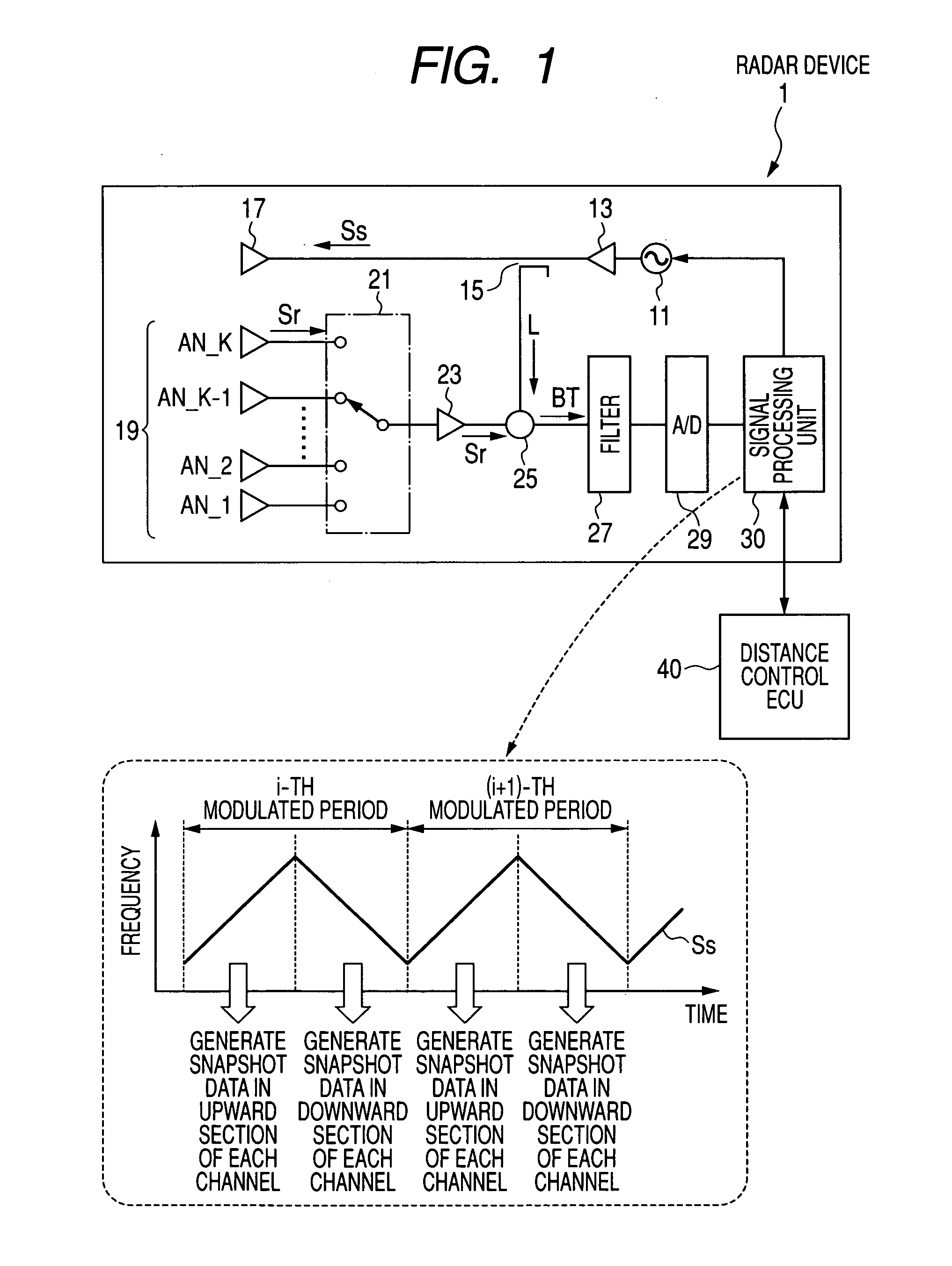
[0077]FIG. 1 is a block diagram showing the structure of the radar device 1 according to the first embodiment of the present invention.

[0078]As shown in FIG. 1, the radar device 1 according to the first embodiment is a FMCW (Frequency Modulated Continuous Wave) type on-vehicle radar device. The radar device 1 is mainly comprised of an oscillator 11, an amplifier 13, a splitter 15, a transmitting antenna 17, and a receiving antenna 19 composed of K antenna elements (K is a positive integer). The oscillator 11 generates a high frequency signal in the millimeter wave band, the frequency of which is linearly and gradually decreased with the elapse of time. The amplifier 13 amplifies the high frequency signal generated by the oscillator 11. The splitter 15 splits the electric power of the output signal supplied from the amplifier 13 into a tr...

second embodiment

[0186]A description will be given of the radar device according to the second embodiment of the present invention with reference to FIG. 5.

[0187]FIG. 5 is a flow chart showing another process of calculating the weighting coefficient performed by the signal processing unit 30 in the radar device 1 according to the second embodiment of the present invention.

[0188]The signal processing unit 30 in the radar device 1 according to the second embodiment performs the weighting coefficient calculating process S160-1 which is different in operation from the weighting coefficient calculating process of step S160 in the first embodiment. Because other operations of the second embodiment are the same as those in the first embodiment, the explanation of the same processes is omitted here for brevity.

[0189]In the second embodiment, one of K channels from the first channel to the K-th channel is used as a representative channel which is determined in advance in the design work.

[0190]When starting t...

third embodiment

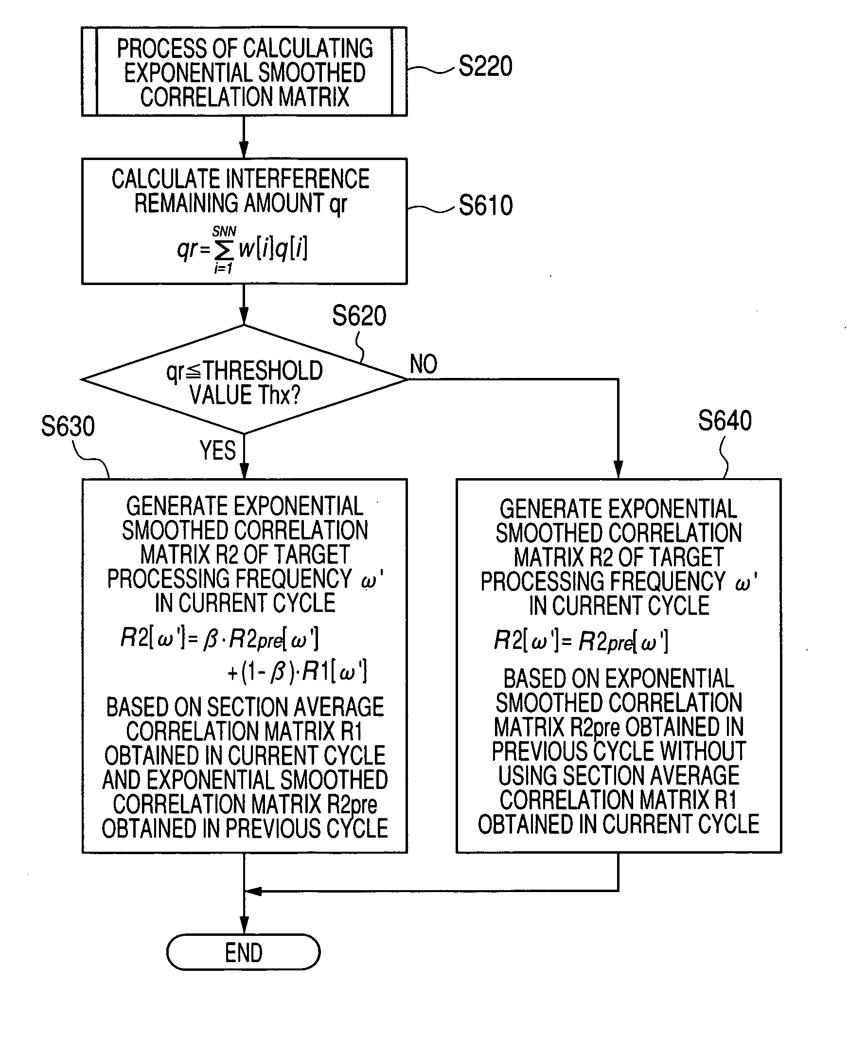
[0202]A description will be given of the radar device according to the third embodiment of the present invention with reference to FIG. 6.

[0203]Because the processes of the third embodiment other than the weighting coefficient calculating process performed in step S160 are same as those in the first embodiment, the weighting coefficient calculating process will be mainly explained.

[0204]FIG. 6 is a flow chart showing another process of calculating the weighting coefficient performed by the signal processing unit in the radar device 1 according to the third embodiment.

[0205]When starting the weighting coefficient calculating process shown in FIG. 6, the signal processing unit 30 executes the series of steps S510 to S560, like the first embodiment. When the detection result in step S550 indicates that the variable i=SNN (“Yes” in step S550), the operation flow progresses to step S572. In step S572, the signal processing Unit 30 calculates the weighting coefficient w[i] by the followin...


PUM


Abstract

A FMCW-type radar device generates snapshot data from a beat signal that represents a received condition of the radar device every modulation period. Auto-correlation matrices generated by the snapshot data every modulation period are averaged every set of plural periods. The radar device calculates the target azimuth of a target object such as a preceding vehicle based on the averaged auto-correlation matrix based on MUSIC (MUltiple SIgnal Classification) method. This averaging is performed by weighting average based on an amount of mixed noise (or an interference amount) contained in the snapshot data in each modulation period. A weighting coefficient to be applied to the auto-correlation matrix in each modulation period is set to a value corresponding to the amount of mixed noise, namely, the interference amount of this modulation period. The weighting coefficient becomes large when the interference amount is small, and on the other hand, becomes small when it is large.

Description

CROSS-REFERENCE TO RELATED APPLICATION[0001]This application is related to and claims priority from Japanese Patent Application No. 2008-243145 filed on Sep. 22, 2008, the contents of which are hereby incorporated by reference.BACKGROUND OF THE INVENTION[0002]1. Field of the Invention[0003]The present invention relates to a radar device capable of transmitting a radar wave and receiving a reflected radar wave (as an arrival wave), and obtaining target information regarding a target position, a traveling (moving) speed, and a target azimuth (or the direction) of the target object based on received signals, corresponding to the reflected radar wave, obtained through an array antenna.[0004]2. Description of the Related Art[0005]There are various types of known conventional radar devices, for example, one of which is mounted to one's own vehicle (hereinafter, referred to as the “driver's vehicle”), and generates and transmits a transmission radar wave as an observation signal toward the...

Claims


Application Information

Patent Timeline
IPC IPC(8): G01S13/42G01S13/00G01S13/08
CPCG01S3/74G01S13/345G01S2013/9375G01S13/931G01S13/42G01S2013/93271
Inventor SAKAMOTO, MAINATSUME, KAZUMAWATANABE, YUUSHIRAI, HIDEKIYAMANO, CHIHARU
Owner DENSO CORP
Why Eureka
Try Eureka