
Image Processing Device And Electric Apparatus

Inactive Publication Date: 2010-03-25
SANYO ELECTRIC CO LTD
View PDF41 Cites 22 Cited by
  • Summary
  • Abstract
  • Description
  • Claims
  • Application Information

AI Technical Summary

Benefits of technology

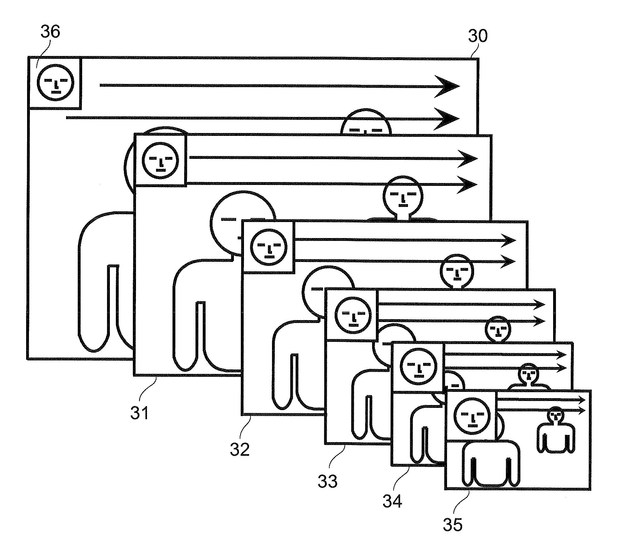
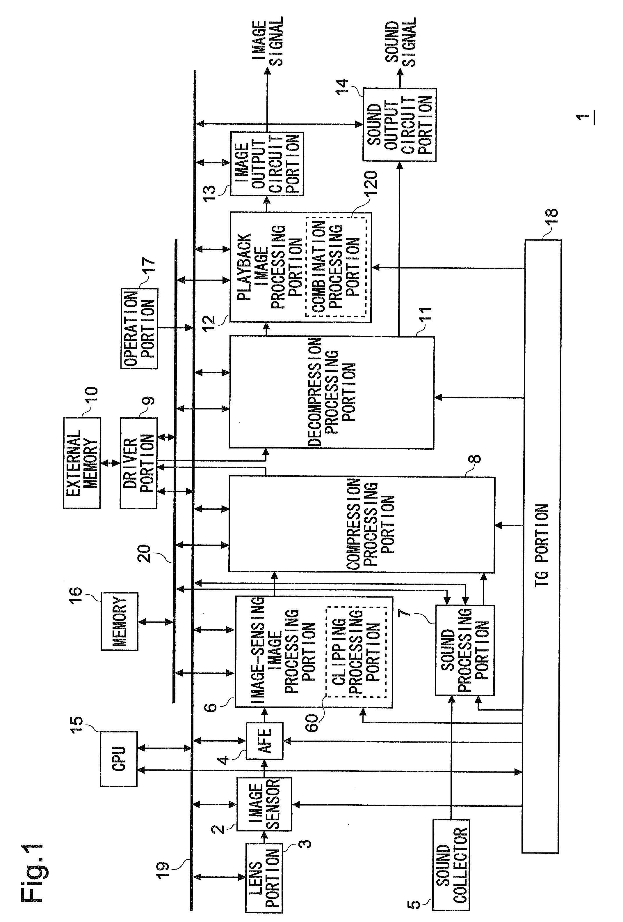
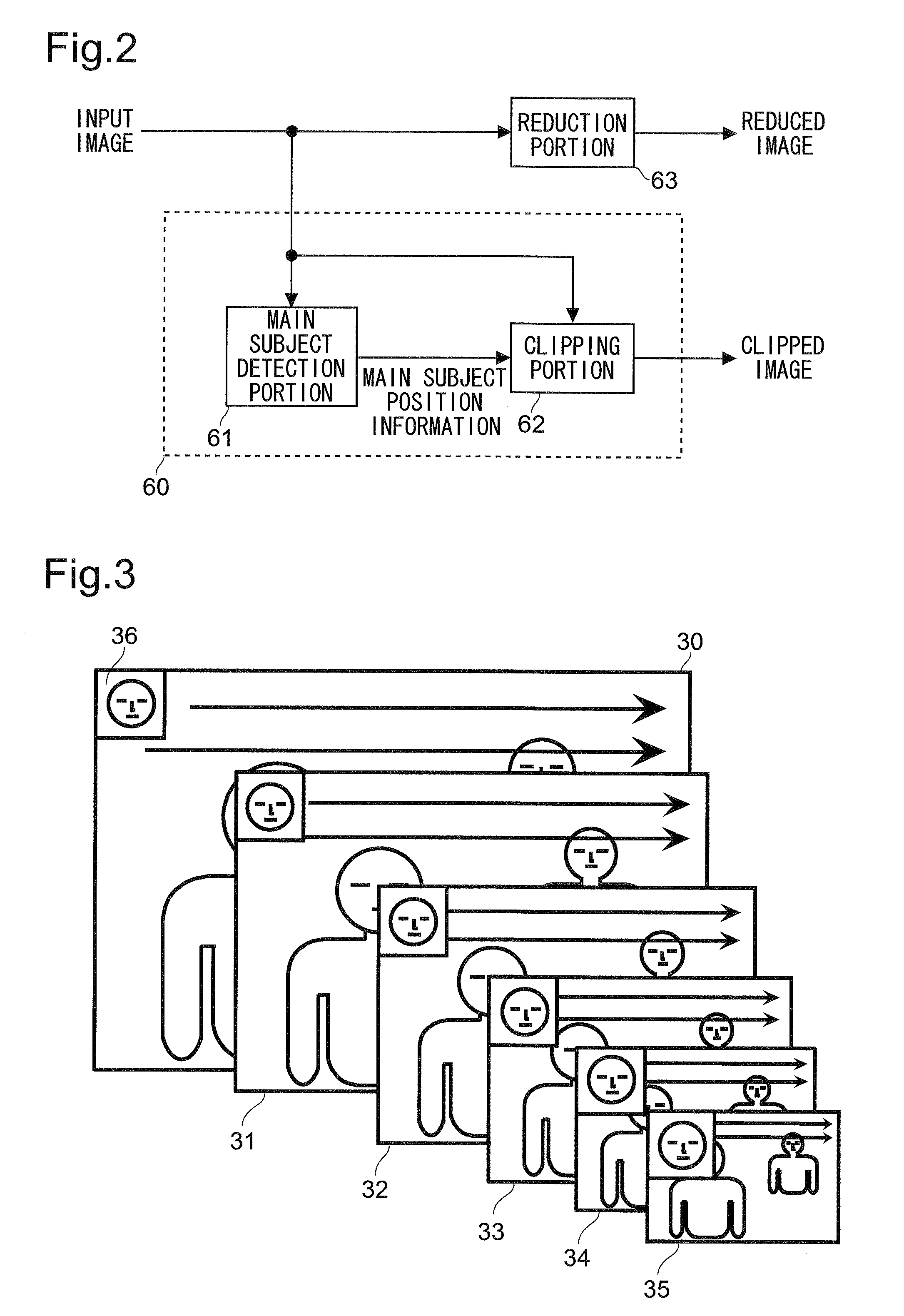
[0010]According to one aspect of the present invention, there is provided an image processing device including: an enlargement processing portion enlarging a reduced image obtained by reducing an input image to generate an enlarged image; a combination portion combining a clipped image that is an image clipped from a clip reg

Problems solved by technology

Disadvantageously, however, when the clipped image is only recorded, it is impossible to obtain a desired image if the clipping processing is improperly performed.
In particular, even if the user wishes to check the image of regions other than the clipped region, since the image of the regions other than the clipped region is not recorded, the image of the regions cannot be checked on playback, with the result that this becomes a problem.
Disadvantageously, however, when a plurality of images are recorded simultaneously, the amount of data recorded is increased, with the result that it is time-consuming to perform different types of processing.
Thus, it is troublesome to check the images.

Method used


Image

  • Image Processing Device And Electric Apparatus
  • Image Processing Device And Electric Apparatus
  • Image Processing Device And Electric Apparatus

Examples


modified examples

[0125]Although, in the above-described example, the enlargement portion 121 in the combination processing portion 120 performs, for example, the interpolation processing so that the number of pixels of the reduced image that is input is increased, in addition to (or instead of) the interpolation processing, super-resolution processing may be performed.

[0126]When the super-resolution processing is performed, it is possible to enhance the quality of the enlarged image that is obtained. Thus, it is possible not only to enhance the accuracy with which the angle-of-view setting portion 123 detects the main subject but also to enhance the quality of the angle-of-view resetting image (after the adjustment) output from the combination processing portion 120. The following description discusses a case where a MAP (maximum a posterior) method that is one type of super-resolution processing is used; such a case will be described with reference to the accompanying drawings. FIGS. 15A to 15D and...


PUM


Abstract

A combination processing portion is provided with: an enlargement portion that enlarges a reduced image obtained by reducing an input image to output an enlarged image; a combination portion that combines together a clipped image generated by clipping a portion of the input image and the enlarged image to generate a combined image; an angle-of-view setting portion that sets a playback angle-of-view region; an on-playback clipping portion that clips the playback angle-of-view region from the combined image to generate an angle-of-view resetting image; and an image size adjustment portion that adjusts the size of the angle-of-view resetting image output from the on-playback clipping portion.

Description

[0001]This nonprovisional application claims priority under 35 U.S.C. §119(a) on Patent Application No. 2008-245665 filed in Japan on Sep. 25, 2008, the entire contents of which are hereby incorporated by reference.BACKGROUND OF THE INVENTION[0002]1. Field of the Invention[0003]The present invention relates to an image processing device that clips a portion of an input image to obtain a desired clipped image and an electronic apparatus incorporating such an image processing device.[0004]2. Description of the Related Art[0005]In recent years, image sensing devices, such as a digital still camera and a digital video camera, that sense an image with an image sensor such as a CCD (charge coupled device) or a CMOS (complimentary metal oxide semiconductor) sensor and display devices, such as a liquid crystal display, that display an image have been widely used. As these sensing devices and display devices, there are provided devices that clip a predetermined region from an image to be pro...

Claims


Application Information

Patent Timeline
IPC IPC(8): H04N5/225
CPCG06T11/60H04N1/3875H04N5/23219H04N5/2621H04N5/772H04N2101/00H04N21/4312H04N21/4314H04N21/4334H04N21/440263H04N21/8153H04N21/4223H04N23/611
Inventor MORI, YUKIO
Owner SANYO ELECTRIC CO LTD
Learn More