Method and system for encoding an image signal, encoded image signal, method and system for decoding an image signal

a technology of encoded image and image signal, applied in the field of method and system for encoded image signal, method and system for decoding image signal, can solve the problems of more visible and annoying, still quite visible artifacts, and experiments with state-of-the-art codec ffmpeg that are not satisfactory, so as to reduce the effect and facilitate the optimization of the derived imag

Inactive Publication Date: 2010-03-25
KONINKLIJKE PHILIPS ELECTRONICS NV
View PDF6 Cites 25 Cited by
  • Summary
  • Abstract
  • Description
  • Claims
  • Application Information

AI Technical Summary

Benefits of technology

[0007]It is an object to provide a method and system for encoding an image signal, an encoded image signal and a method and system for decoding an encoded image signal which can inter alia be used to yield better quality images for an amount of compression (in particular in gradual regions such as the sky), and furthermore allows other applications to perform better.

Problems solved by technology

One type of artifacts frequently occurs in the coding of smooth gradual-transition areas within an image.
These artifacts are mainly caused by quantization during encoding and other information loss during the encoding procedure and is more visible and annoying than at more textured areas.
However experiments with state-of-the-art codec FFMPEG do not give satisfactory results, with still quite visible artifacts at even low QPs.
In circumstances, for instance when only a limited amount of data space is available, this will form a problem.
However, experiments in which use was made of already in-loop de-blocking filters showed that the artifacts were not removed, probably due to the large extent of the gradual-transition areas.
1. It is difficult to determine completely at the decoder side where to apply the post-filtering. Since the encoded gradual-transition areas are already distorted (not smooth anymore), it is very difficult to know whether the original frame is smooth or not.
2. Post-filtering requires the selection of the right filter parameters (aperture size, etc) to avoid over- or under-filtering. The type of filters to use is determined by many factors, such as the extent of the area and the strength of the artifacts, which can be influenced by encoding parameters such as quantization parameters. However, the inventors have found that even manual tuning of parameters cannot lead to desired results. Furthermore, this type of filtering can hardly remove the temporal artifacts occurring in gradual-transition areas.

Method used


Image

  • Method and system for encoding an image signal, encoded image signal, method and system for decoding an image signal
  • Method and system for encoding an image signal, encoded image signal, method and system for decoding an image signal
  • Method and system for encoding an image signal, encoded image signal, method and system for decoding an image signal

Examples


Embodiment Construction

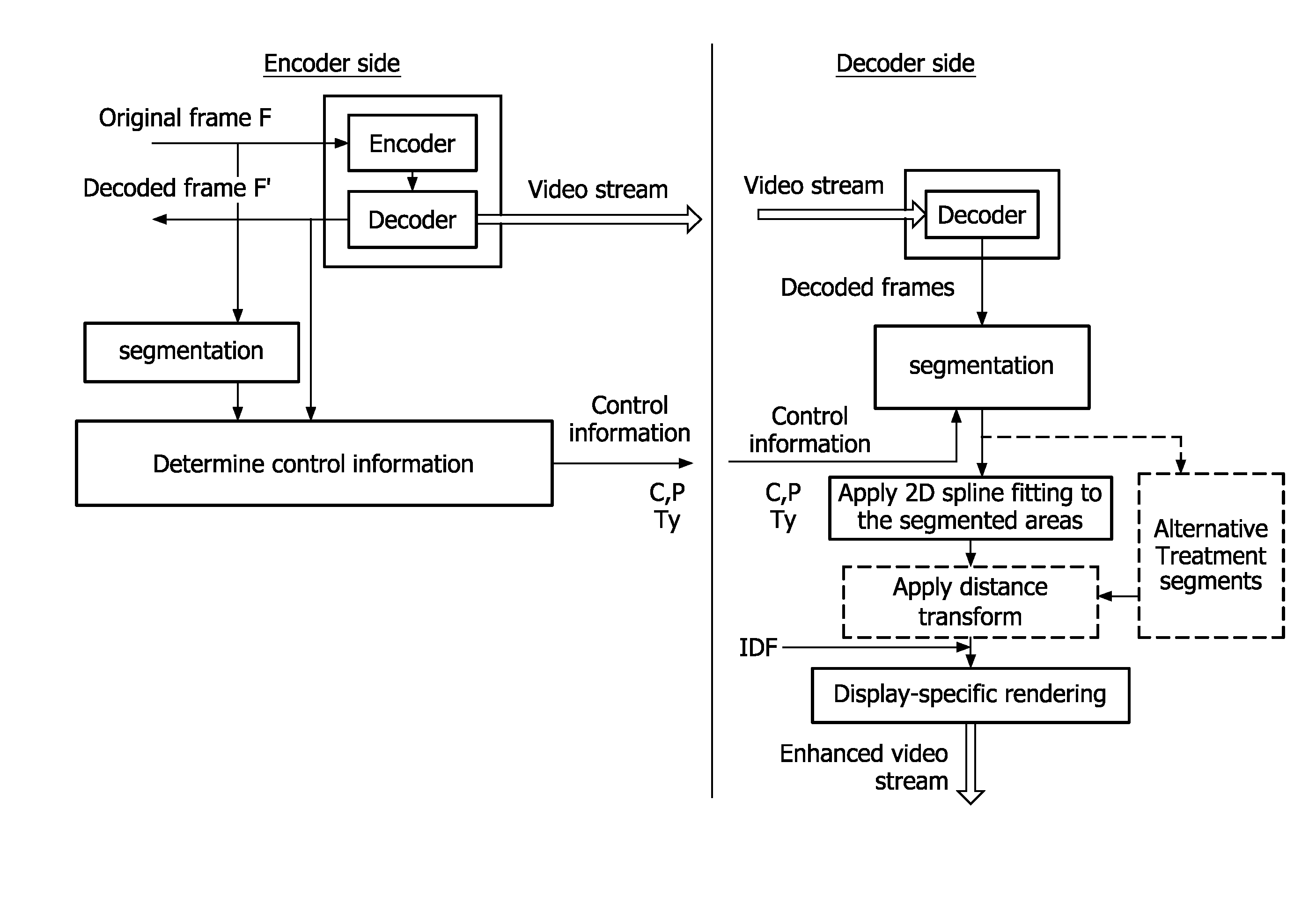
[0036]FIG. 1 shows a processing flow of an embodiment of our invention used as a post-processing method. This is illustrated in the following:

Encoder Side:

[0037]1. Encode frame F and obtain its corresponding decoded frame F'.

2. Detection of gradual-transition areas in frame F. Frame F is then the first image frame, frame F′ the derived image frame.

[0038]For frame F, first mark all pixels as unprocessed. Scan frame F in the order of left-to-right and top-to-bottom. If pixel at location (xs, ys) is unprocessed, select it as a seed, and apply a floodfill algorithm. The algorithm starts from the selected seed and grows the area as long as the luminance difference between adjacent pixels does not exceed a predefined threshold T. This threshold can be set as a small number (e.g. 3). This is because gradual-transition areas in original frame have the characteristics that neighboring pixels in these areas have very similar luminance values (although the whole area can have a wide distributi...


PUM


Abstract

An image signal is encoded to reduce artifacts. In an original image frame (F) one or more gradual transition areas (R) are identified, in a decoded frame (F) corresponding one or more gradual transition areas (R) are identified, functional parameters describing the data content of the one or more gradual transition areas of the original image frame are established and position data (P) for the positions of the one or more corresponding areas (R′) in the decoded frame (F′) are established. Replacing the content of the areas R′ in the decoded frame with the reconstructed content of the areas R in the original frame improves the quality of the decoded frame.

Description

FIELD OF THE INVENTION[0001]The invention relates to a method and system for encoding an image signal in which method or system artifact reduction is applied.[0002]The invention also relates to a method and system for decoding an image signal.[0003]The invention also relates to an image signal.DESCRIPTION OF PRIOR ART[0004]In encoding of image signal artifacts occur. One type of artifacts frequently occurs in the coding of smooth gradual-transition areas within an image. These artifacts show as blockiness, color distortion, and wobbling effect during temporal evolution. These artifacts are mainly caused by quantization during encoding and other information loss during the encoding procedure and is more visible and annoying than at more textured areas.[0005]One possible solution to the above problem is to use adaptive quantization, which allocates more bits (using small QP) to the smoother areas and fewer bits on more textured areas. However experiments with state-of-the-art codec FF...

Claims


Application Information

Patent Timeline
Patent Type & Authority Applications(United States)
IPC IPC(8): H04B1/66
CPCH04N19/172H04N19/46H04N19/86H04N19/14H04N19/467H04N19/117
Inventor ZUO, FEIDE WAELE, STIJN
Owner KONINKLIJKE PHILIPS ELECTRONICS NV
Why Eureka
Try Eureka