Trailing Edge Cooling Slot Configuration for a Turbine Airfoil

a technology of turbine airfoil and cooling slot, which is applied in the direction of machines/engines, liquid fuel engines, mechanical equipment, etc., can solve the problems of reducing the useful life of the turbine blade, the likelihood of failure, and localized hot spots

Inactive Publication Date: 2010-03-25
SIEMENS ENERGY INC
View PDF11 Cites 52 Cited by
  • Summary
  • Abstract
  • Description
  • Claims
  • Application Information

AI Technical Summary

Problems solved by technology

In addition, turbine blades often contain cooling systems for prolonging the life of the blades and reducing the likelihood of failure as a result of excessive temperatures.
However, centrifugal forces and air flow at boundary layers often prevent some areas of the turbine blade from being adequately cooled, which results in the formation of localized hot spots.
Localized hot spots, depending on their location, can reduce the useful life of a turbine blade and can damage a turbine blade to an extent necessitating replacement of the blade.
Operation of a turbine engine results in high stresses being generated in numerous areas of a turbine blade.
Because the trailing edge is relatively thin and an area prone to development of high stresses during operation, the trailing edge is highly susceptible to formation of cracks which may lead to failure of the airfoil.
In some turbine stage blading designs, a larger trailing edge thickness may induce high blockage and thus reduce the stage performance.
Hence, the size and space limitations make the trailing edge of gas turbine airfoils one of the most difficult areas to cool.
This type of cooling concept is effective to reduce the airfoil trailing edge thickness, but results in shear mixing between the cooling fluid and the mainstream flow as the cooling fluid exits from the airfoil pressure side.
The shear mixing of the cooling fluid with the mainstream flow reduces the cooling effectiveness in the area of the trailing edge overhang and thus may result in an overtemperature condition on the suction side of the airfoil.
Frequently, the deterioration of trailing edge overhang area due to overtemperature conditions becomes a limiting condition for the service life of the entire airfoil.

Method used


Image

  • Trailing Edge Cooling Slot Configuration for a Turbine Airfoil
  • Trailing Edge Cooling Slot Configuration for a Turbine Airfoil
  • Trailing Edge Cooling Slot Configuration for a Turbine Airfoil

Examples


Embodiment Construction

[0018]In the following detailed description of the preferred embodiment, reference is made to the accompanying drawings that form a part hereof, and in which is shown by way of illustration, and not by way of limitation, a specific preferred embodiment in which the invention may be practiced. It is to be understood that other embodiments may be utilized and that changes may be made without departing from the spirit and scope of the present invention.

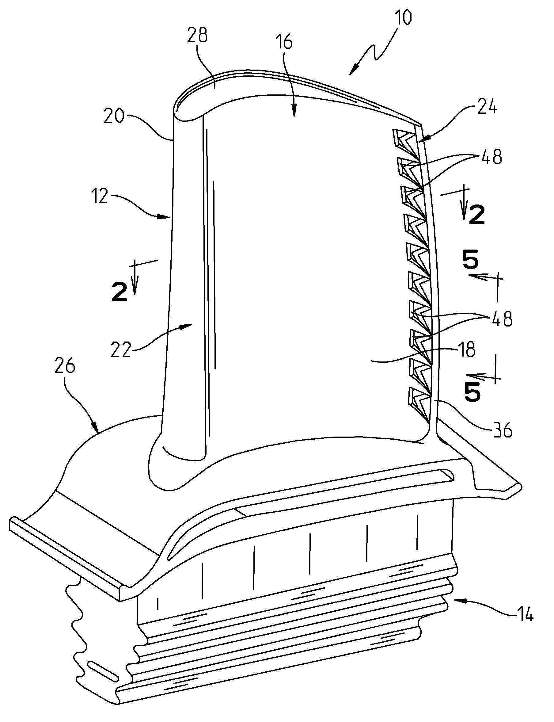
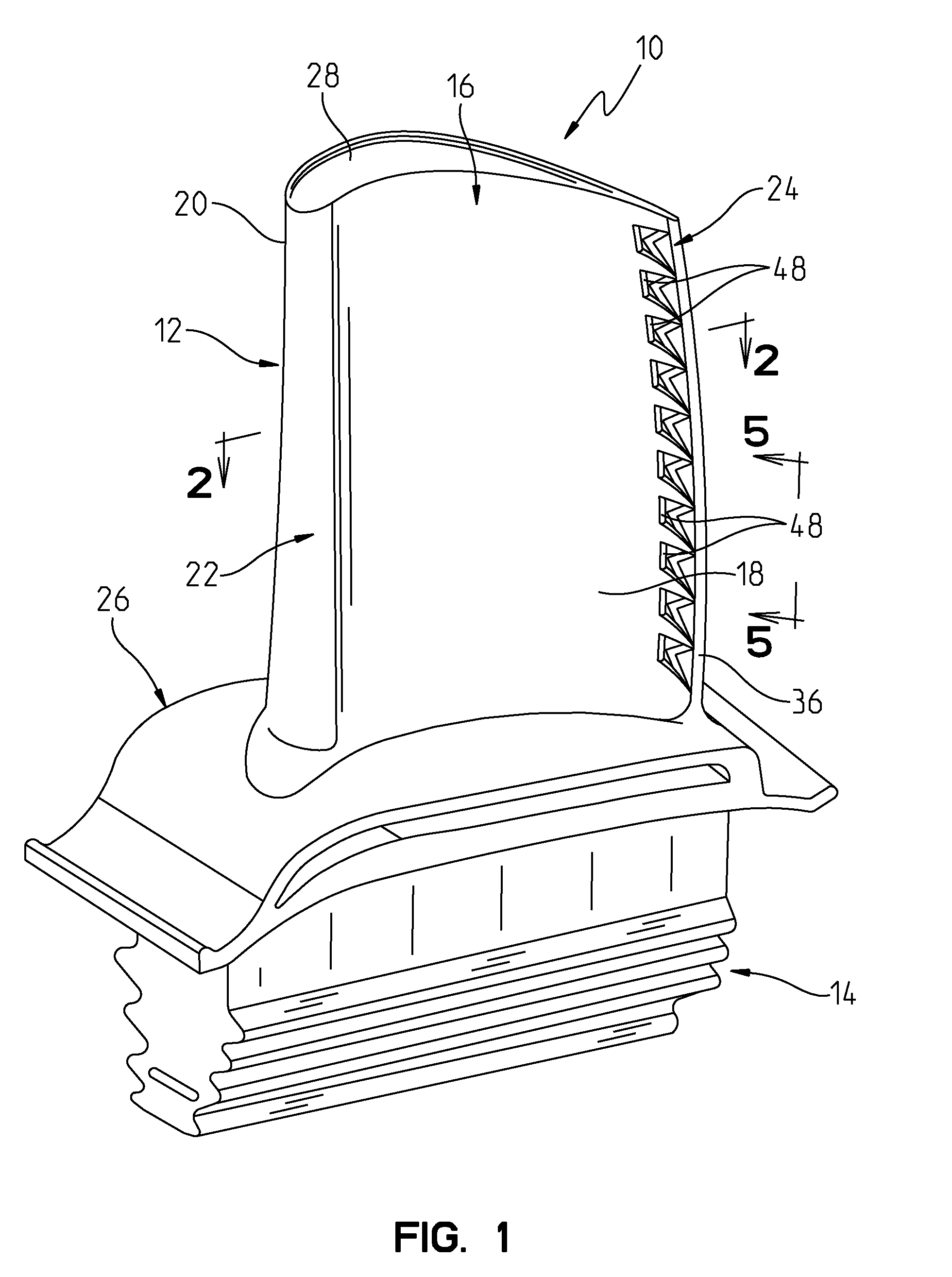
[0019]Referring to FIG. 1, an exemplary turbine blade 10 for a gas turbine engine is illustrated in accordance with the present invention. It should be understood that although the present invention is described with specific reference to the illustrated blade 10, the invention may be implemented in similar turbine structure such as a turbine vane airfoil. The blade 10 includes an airfoil 12 and a root 14 which is used to conventionally secure the blade 10 to a rotor disk of the engine for supporting the blade 10 in the working medium fl...


PUM


Abstract

A gas turbine engine hollow turbine airfoil having pressure and suction sidewalls extending chordwise between leading and the trailing edges. The trailing edge includes a pressure sidewall lip and a suction sidewall lip, and a breakout distance between the pressure sidewall lip and the suction sidewall lip. A cooling fluid channel extends spanwise through the airfoil for supplying a cooling fluid to the airfoil. Flow channels are provided extending chordwise between the cooling fluid channel and the suction sidewall lip and include a metering section, an internal diffusion section and a breakout slot. The interior diffusion section includes a spanwise dimension and a widthwise dimension perpendicular to the spanwise dimension, wherein the spanwise dimension continuously increases extending in the chordwise direction, and the widthwise dimension continuously decreases extending in the chordwise direction.

Description

CROSS-REFERENCE TO RELATED APPLICATION[0001]This application claims the benefit of U.S. Provisional Application Ser. No. 61 / 100,121, entitled METHOD OF FORMING A AIRFOIL TRAILING EDGE COOLING SLOT, filed Sep. 25, 2008, the entire disclosure of which is incorporated by reference herein.FIELD OF THE INVENTION[0002]This invention is directed generally to turbine airfoils and, more particularly, to turbine airfoils having cooling fluid passages for conducting a cooling fluid to cool a trailing edge of the airfoil.BACKGROUND OF THE INVENTION[0003]A conventional gas turbine engine includes a compressor, a combustor and a turbine. The compressor compresses ambient air which is supplied to the combustor where the compressed air is combined with a fuel and ignites the mixture, creating combustion products defining a working gas. The working gas is supplied to the turbine where the gas passes through a plurality of paired rows of stationary vanes and rotating blades. The rotating blades are c...

Claims


Application Information

Patent Timeline
Patent Type & Authority Applications(United States)
IPC IPC(8): F01D5/18
CPCF01D5/187F05D2240/122F05D2260/22141F05D2260/202F05D2240/304
Inventor LIANG, GEORGE
Owner SIEMENS ENERGY INC
Why Eureka
Try Eureka