Integral patterning of large features along with array using spacer mask patterning process flow

Inactive Publication Date: 2010-03-25
APPLIED MATERIALS INC
View PDF12 Cites 282 Cited by
  • Summary
  • Abstract
  • Description
  • Claims
  • Application Information

AI Technical Summary

Benefits of technology

[0006]Embodiments of the present invention pertain to methods of forming patterned features on a substrate having an increased density (i.e. reduced pitch) as compared to what is possible using standard photolithography

Problems solved by technology

Due to factors such as optics and light or radiation wavelength, however, photolithography techniques have a minimum pitch below which a particular photolith

Method used


Image

  • Integral patterning of large features along with array using spacer mask patterning process flow
  • Integral patterning of large features along with array using spacer mask patterning process flow
  • Integral patterning of large features along with array using spacer mask patterning process flow

Examples


Embodiment Construction

[0019]Embodiments of the present invention pertain to methods of forming patterned features on a substrate having an increased density (i.e. reduced pitch) as compared to what is possible using standard photolithography processing techniques using a single high-resolution photomask while also allowing both the width of the patterned features and spacing (trench width) between the patterned features to vary within an integrated circuit.

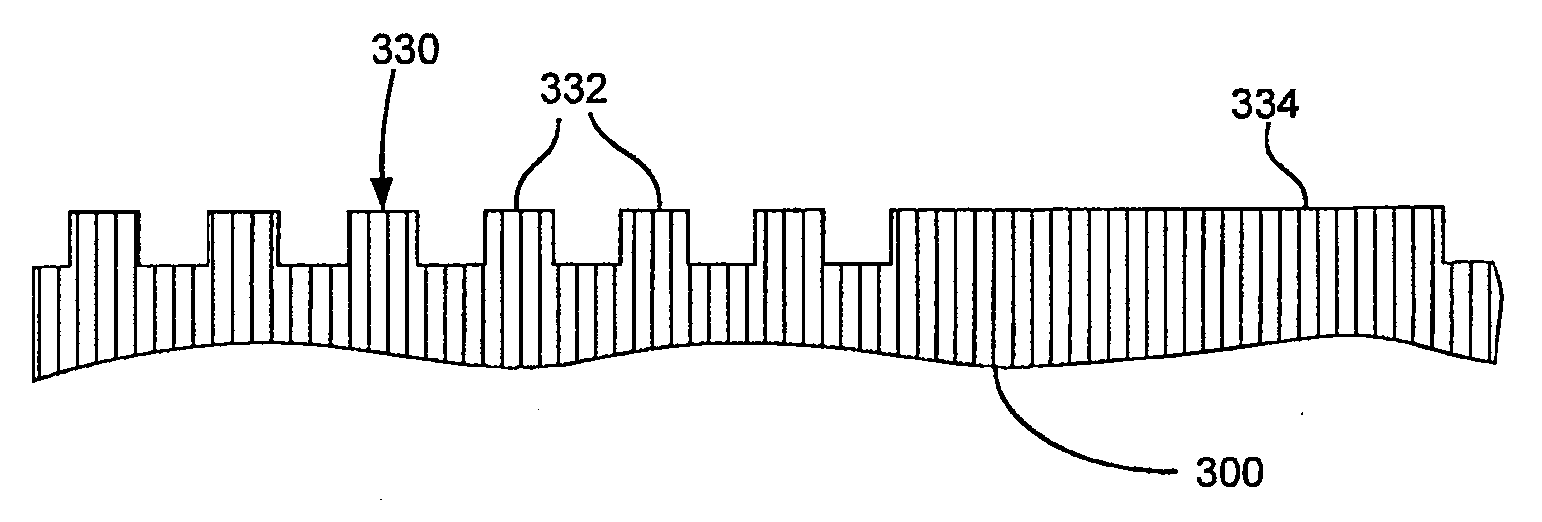
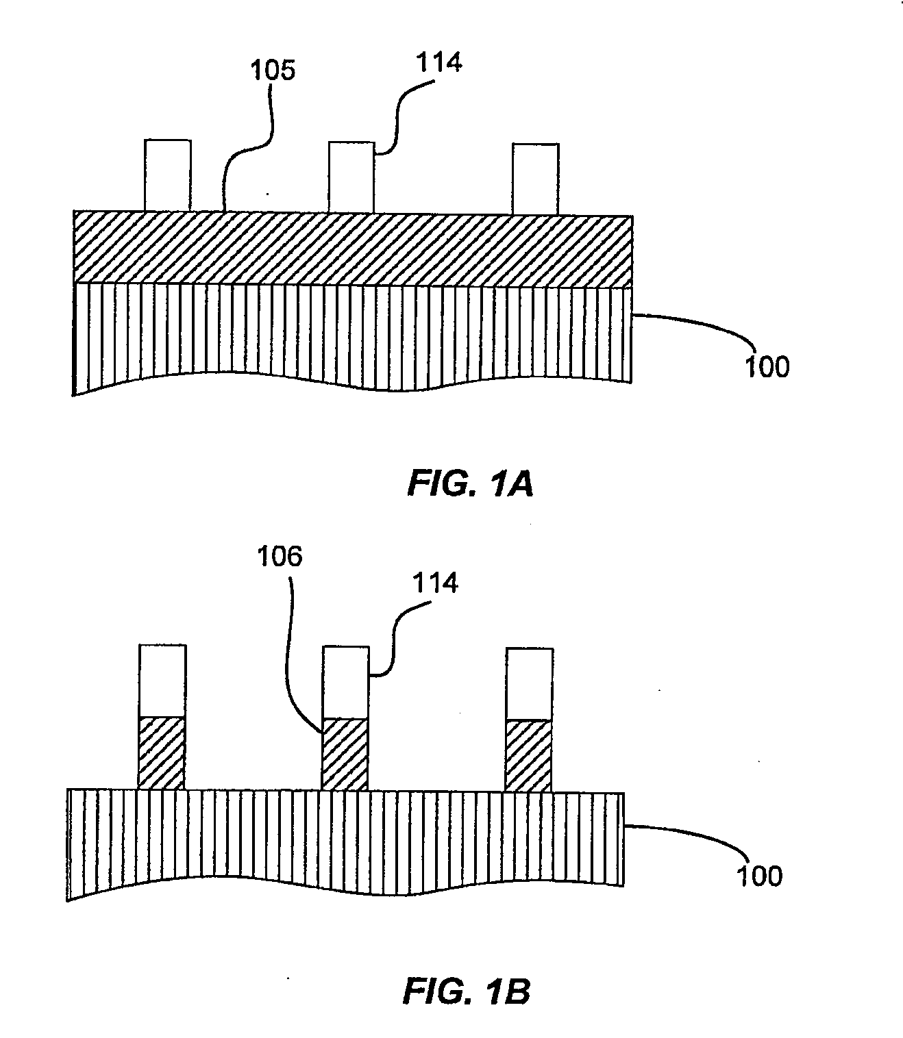
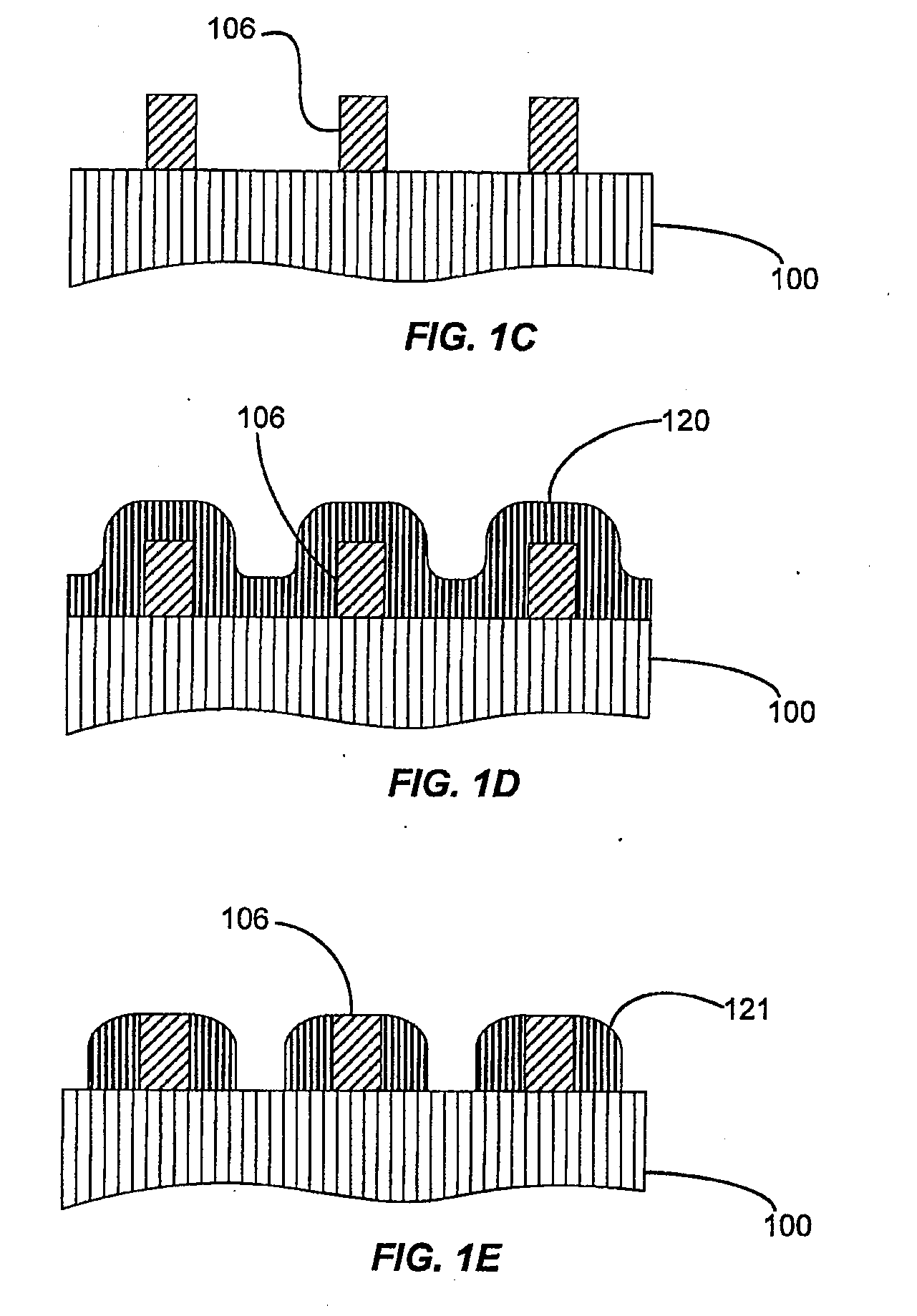
[0020]One of the most common uses of a self-aligned double patterning (SADP) process is to form high density arrays of parallel lines. A positive tone SADP process (such as the process of FIG. 1) uses the spacers as the etch mask, resulting in lines of the same width. While this lends itself readily to forming bit lines, wider lines and features (for example, pads, power supply lines, string select lines, etc.) are usually necessary on the same layer to form working devices. A negative tone SADP process introduces a gapfill material between the spacers...


PUM


Abstract

Embodiments of the present invention pertain to methods of forming patterned features on a substrate having an increased density (i.e. reduced pitch) as compared to what is possible using standard photolithography processing techniques using a single high-resolution photomask while also allowing both the width of the patterned features and spacing (trench width) between the patterned features to vary within an integrated circuit.

Description

BACKGROUND[0001]The application relates generally to substrate processing methods and particularly to process sequences which increase the density of features on the substrate.[0002]Shrinking integrated circuits (ICs) may result in improved performance, increased capacity and / or reduced cost. Each device shrink requires more sophisticated techniques to form the features. Photolithography is commonly used to pattern features on a substrate. An exemplary feature is a line of a material which may be a metal, semiconductor or insulator. Linewidth is the width of the line and the spacing is the distance between adjacent lines. Pitch is defined as the distance between a same point on two neighboring lines. The pitch is equal to the sum of the linewidth and the spacing. Due to factors such as optics and light or radiation wavelength, however, photolithography techniques have a minimum pitch below which a particular photolithographic technique may not reliably form features. Thus, the minim...

Claims


Application Information

Patent Timeline
IPC IPC(8): H01L21/311
CPCH01L21/3086Y10S438/95H01L21/3088H01L21/0338
Inventor BENCHER, CHRISTOPHER DENNISTANG, JING
Owner APPLIED MATERIALS INC
Why Eureka
Try Eureka