Ultrasonic probe

a technology of ultrasonic probes and probes, applied in the field of ultrasonic probes, can solve the problems of difficult design of miniaturized compact probes, affecting the diagnosis of patients, emitting characteristic metallic noises, etc., and achieves the effect of reducing the diagnosis burden on the operator and removing the source of discomfor

Inactive Publication Date: 2010-03-25
NIHON DEMPA KOGYO CO LTD
View PDF6 Cites 19 Cited by
  • Summary
  • Abstract
  • Description
  • Claims
  • Application Information

AI Technical Summary

Benefits of technology

[0023]Since in this configuration there is a pulley linkage using a belt between the rotation shaft of the second bevel gear and the drive motor, and the first bevel gear is made of a synthetic resin, there is no engagement between metal gears and thus there is no generation of the characteristic metallic noise during rotation. This makes it possible to remove a source of discomfort to the operator of the ultrasonic probe and, in particular, to the patient. Moreover, setting of the reference position with respect to the object to be detected of the piezoelectric element group can be facilitated, and hence the diagnosis burden on the operator is considerably reduced.

Problems solved by technology

However, in the short-axis oscillating probe of the prior-art 1 configured as described above, since the first bevel gear 8a and the second bevel gear 8b both made of metal are used, when these metal gears engage, they emit characteristic metallic noises, which raises a problem in that it causes discomfort to the doctor (operator) and, in particular, to the patient, during operation.
Since the pulley on the piezoelectric element side is thus increased in size, it is difficult to design a miniaturized compact probe.
Therefore, there is the problem in that a metallic noise occurs at the time of meshing and rotating of the pair of metal gears.

Method used


Image

  • Ultrasonic probe
  • Ultrasonic probe
  • Ultrasonic probe

Examples


Embodiment Construction

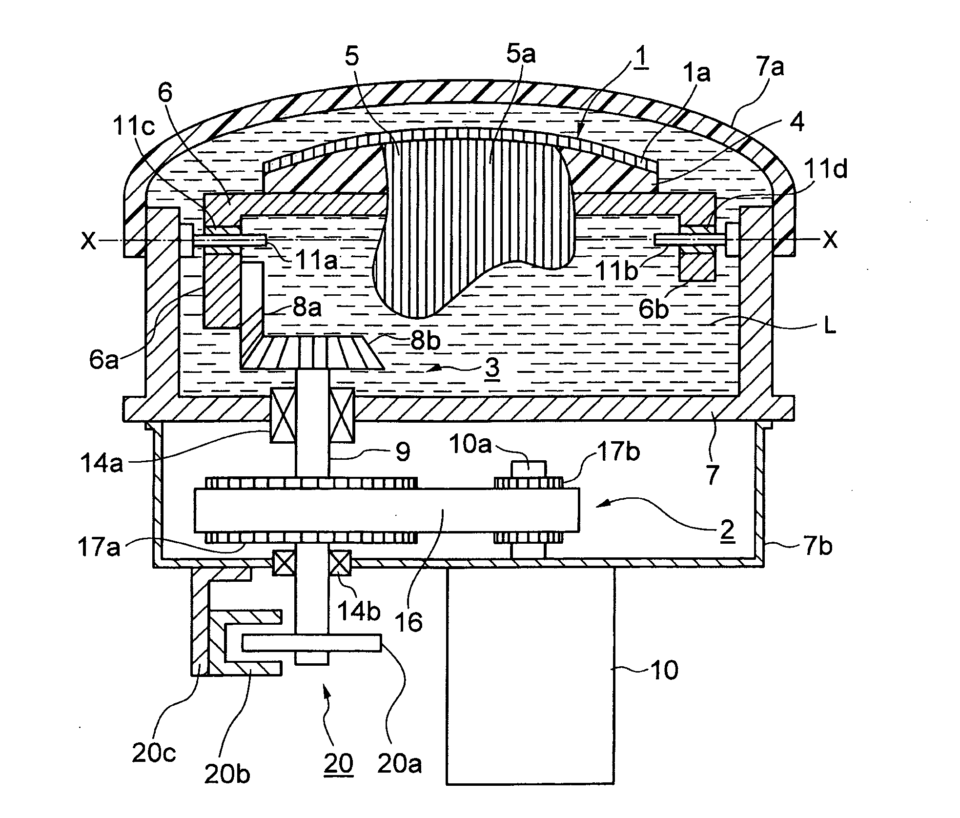
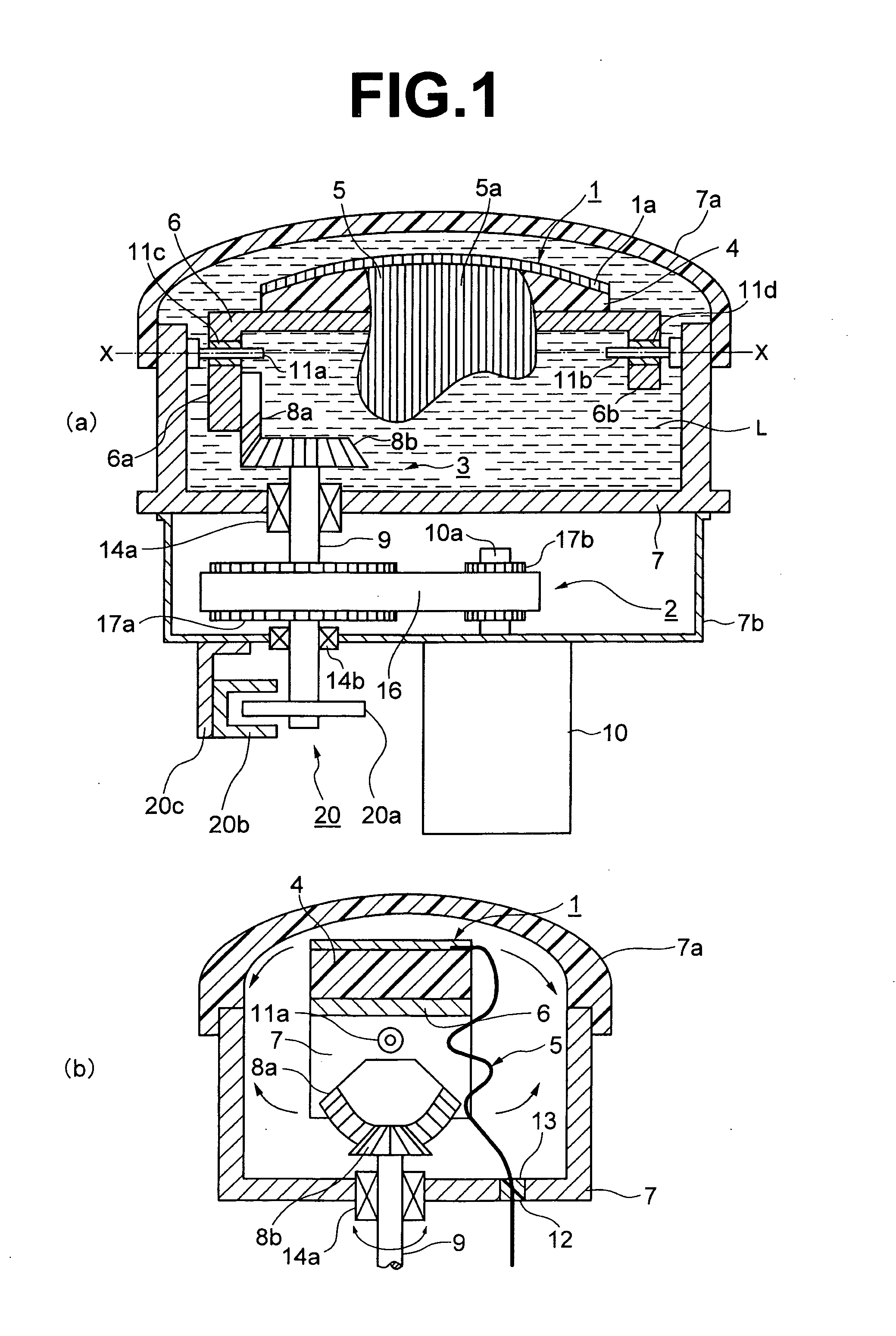
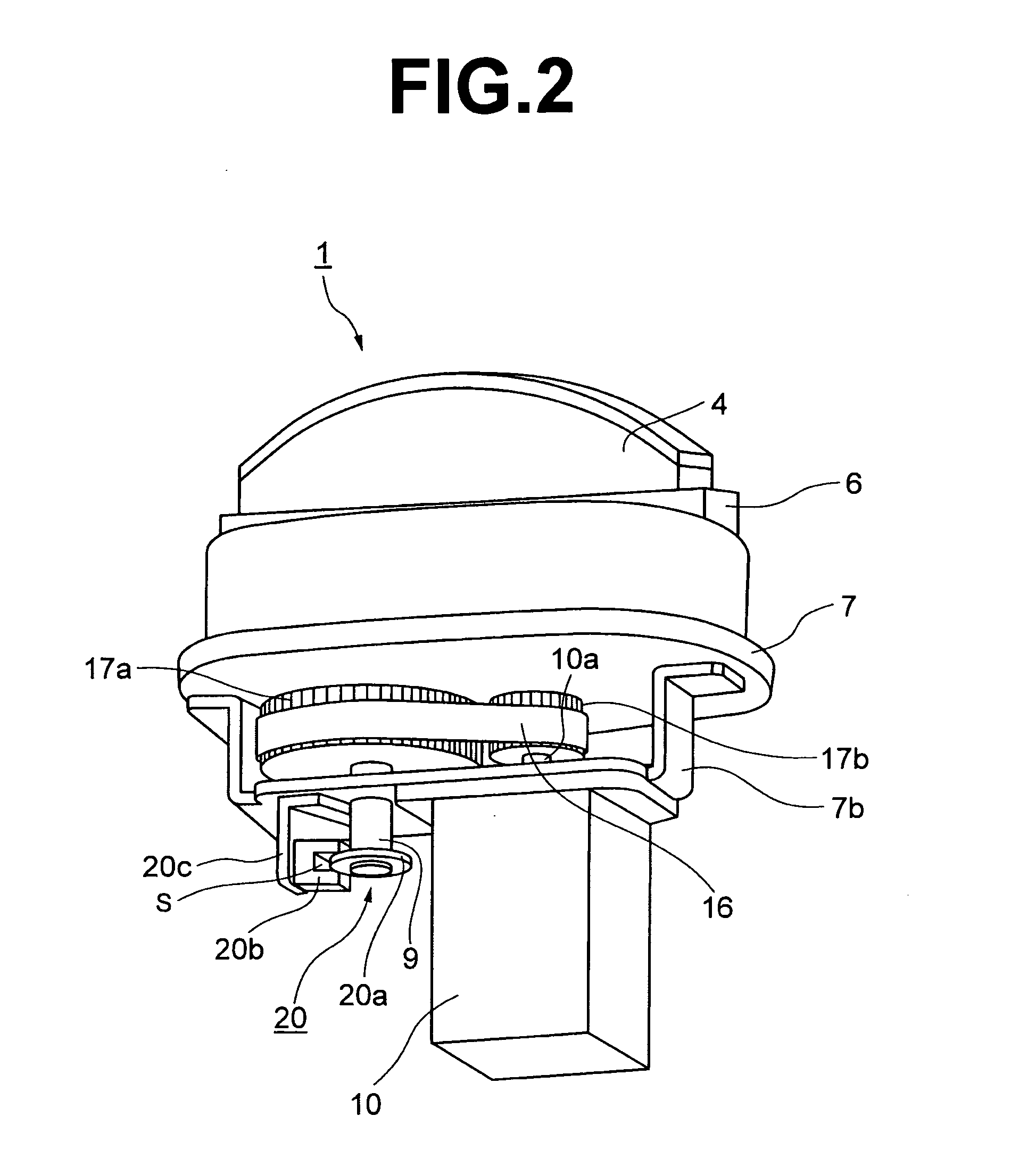
[0029]FIG. 1A is a drawing for explaining an embodiment of a short-axis oscillating probe of the present invention, being a cross-section in the long axis direction. FIG. 1B is a transverse section in the short axis direction, and FIG. 2 is a perspective view thereof.

[0030]The short-axis oscillating probe of the present invention is provided with a group of piezoelectric elements 1, and a rotation mechanism 2 thereof, and a reference position detection sensor 20.

[0031]The group of piezoelectric elements 1 are configured in a convex form side by side on a backing member (not shown in the figure) that is attached to an upper surface of a base 4, with the widthwise direction of a large number of piezoelectric elements 1a in the long-axis direction. A flexible substrate 5 that is connected electrically to the group of piezoelectric elements 1 through a conductive path 5a (in FIG. 5A omitted but shown by partially cutaway lines) is lead out from one end side in the short-axis direction o...


PUM


Abstract

The ultrasonic probe comprises a group of piezoelectric elements including piezoelectric elements arrayed in a long-axis direction thereof; and a rotation mechanism that oscillates the piezoelectric elements to the left and right in a short-axis direction thereof about a center of the long-axis direction. The rotation mechanism has a first bevel gear of a circular-arc shape, a second bevel gear meshing with the first bevel gear and rotating in a horizontal direction, and a drive motor. An optical rotating plate, with the boundary region as a reference, is rotated by less than a predetermined angle, and the boundary region is detected by transmission or shielding of light by the light shielding portion and the light transmission portion, and thereby, based on the detected boundary region, a reference position with respect to an object to be detected of the piezoelectric element group is set.

Description

CROSS-REFERENCE TO RELATED APPLICATIONS[0001]The present application is a continuation-in-part of co-pending U.S. application Ser. No. 11 / 879,909 filed Jul. 19, 2007, which is incorporated herein by reference in its entirety.BACKGROUND OF THE INVENTION[0002]The present invention relates to an ultrasonic probe in which a group of piezoelectric elements that is a source of ultrasonic waves oscillates in the short-axis direction to obtain a three-dimensional image (hereinafter called a “short-axis oscillating probe”) and, in particular, to a short-axis oscillating probe having a simple configuration in which the operational noise of the probe while operating is minimized to remove that source of discomfort to the patient, and in which a mechanism of detection of a rotation angle of a piezoelectric group is simplified, and detection of a reference position thereof with respect to an object to be detected is facilitated.[0003]1. Field of the Invention[0004]A short-axis oscillating probe ...

Claims


Application Information

Patent Timeline
Patent Type & Authority Applications(United States)
IPC IPC(8): A61B8/00
CPCG01N29/06G01N29/225G01N2291/02483G10K11/355G01S15/8906G01S15/894G01S7/52079
Inventor HASEGAWA, YASUNOBU
Owner NIHON DEMPA KOGYO CO LTD
Why Eureka
Try Eureka