Method of positioning containers in a container processing installation, a corresponding positioning device, and an installation including such devices

Inactive Publication Date: 2010-04-01
SERAC GROUP
View PDF4 Cites 32 Cited by
  • Summary
  • Abstract
  • Description
  • Claims
  • Application Information

AI Technical Summary

Benefits of technology

[0011]An object of the invention is to propose means enabling containers to be positioned in a processing installa

Problems solved by technology

The operations for adapting the installations to fit each mouth segment cross-section are lengthy and require the installations to be stop

Method used


Image

  • Method of positioning containers in a container processing installation, a corresponding positioning device, and an installation including such devices
  • Method of positioning containers in a container processing installation, a corresponding positioning device, and an installation including such devices
  • Method of positioning containers in a container processing installation, a corresponding positioning device, and an installation including such devices

Examples


first embodiment

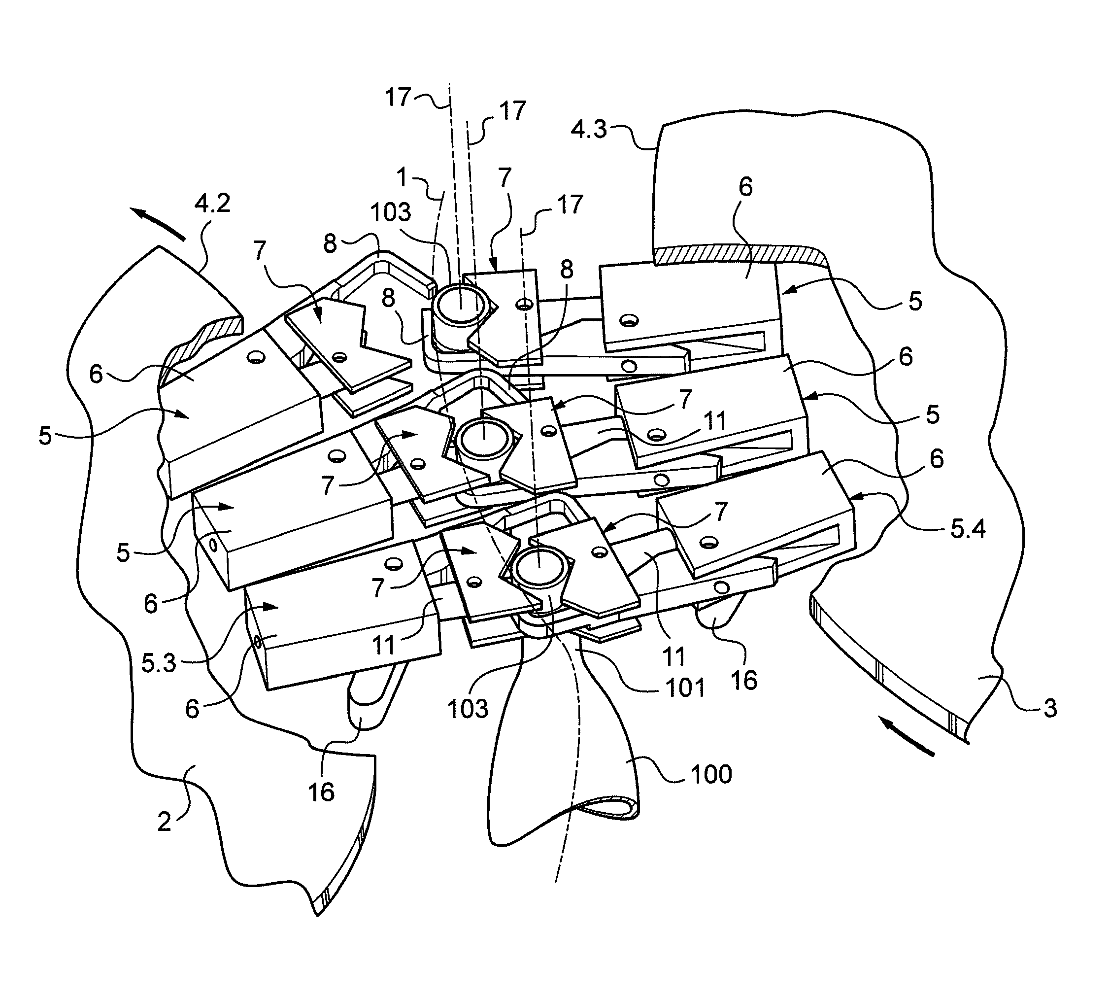
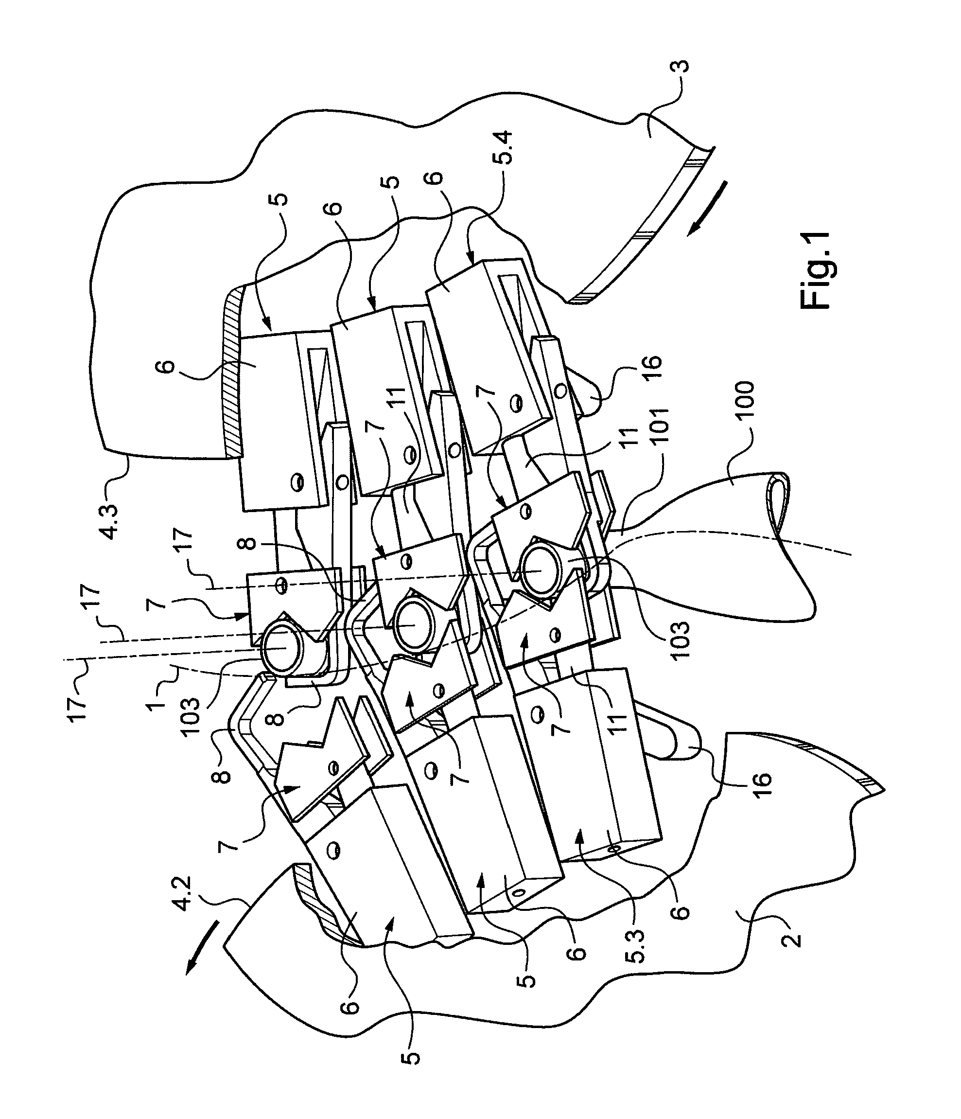
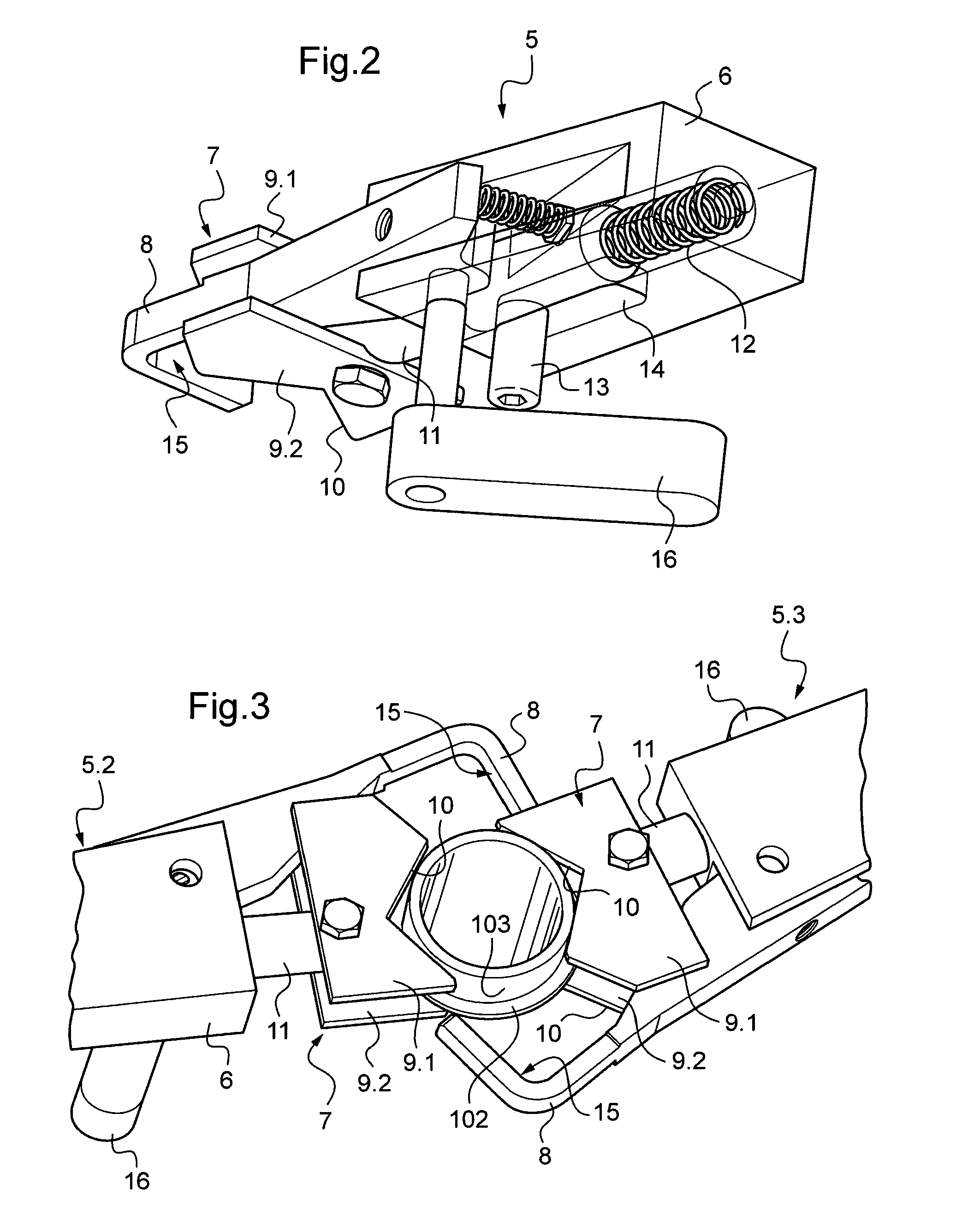
[0045]In the first embodiment, shown in FIGS. 1 to 10, the positioning device 5 comprises a body 6 mounted under the corresponding platform 2, 3, a jaw 7 mounted to slide on the body 6, and a finger 8 mounted to pivot on the body 6.

[0046]The jaw 7 comprises a top plate 9.1 and a bottom plate 9.2 that extend parallel to and facing each other while being spaced apart from each other. The spacing between the plates 9.1 and 9.2 is such that:[0047]the collar can be inserted in part between the plates 9.1, 9.2 and can rest on the bottom plate 9.2;[0048]the bottom plate 9.2 can bear laterally against the portion of the neck that is situated immediately under the collar 102;[0049]the top plate 9.1 can bear laterally against a portion of the mouth segment 103 that is situated above the collar 102.

[0050]Each plate 9.1, 9.2 has an edge in which a cutout 10 is provided for receiving the neck 101 of a container (the faces of the cutouts 10 form bearing faces via which the jaw bears against the n...

second embodiment

[0073]In the second embodiment, shown in FIG. 11 (the upstream platform 2 is situated on the right), the device comprises, as above, a body 6 slidably receiving a jaw 7 so that said jaw can slide between a maximum deployed position, back into which it is resiliently urged, and a minimum deployed position. The structure of the jaw 7 merely comprises a single bottom plate, but it can be identical to the above-described jaw.

[0074]The abutment corresponding to each platform is formed by a guide rail 25.2, 25.3 that is fastened to the structure of the installation on the movement line slightly above the jaw 7. The guide rail 25.2, 25.3 surrounds the platform 2, 3 in question between the feed zone for feeding in containers and the removal zone for removing the containers, so that the jaws 7 push the mouth segments against a face of the guide rail 25.2, 25.3 (forming a reference face) under the action of the return springs that urge the jaws back to their maximum deployed positions.

[0075]T...

third embodiment

[0088]The reference face can also be formed by the bearing surface of the jaw, in particular in the


PUM

PropertyMeasurementUnit
Angleaaaaaaaaaa

Abstract

A method of positioning containers in an installation for processing containers having mouth segments (103) of different cross-sections, the method comprising the step of moving the containers along a container movement line (1) in an installation while maintaining a reference point on each of the mouth segments on said movement line, the movement line being common to all mouth segment cross-sections, and the reference points on the mouth segments being the same regardless of the cross-sections of the mouth segments of the containers, wherein the reference point is situated on an outside side surface of the mouth segment in a manner such that the mouth segments are tangential to the movement line.
A corresponding positioning device and an installation including such devices.

Description

[0001]The present invention relates to a method of positioning containers in a container processing installation such as an installation for packaging a substance in containers, or an installation for conveying, filling, or capping containers. The invention also relates to a positioning device, and to an installation including such devices.BACKGROUND OF THE INVENTION[0002]Consideration is given more particularly herein to containers of the type having a neck provided with a projecting collar below a mouth segment.[0003]An installation for packaging liquids defines a container movement line along which various installations are disposed in succession, such as a filling installation, a capping installation, and optionally an installation for washing or rinsing the containers, a sterilization installation, etc.[0004]For example, a container filling installation comprises a rotary platform having a periphery equipped with filler nozzles and with positioning devices for positioning the c...

Claims


Application Information

Patent Timeline
IPC IPC(8): B65B35/46B65B1/04B65B3/04
CPCB65G47/847B67C7/0053B67C3/242
Inventor GOURLAOUEN, XAVIER
Owner SERAC GROUP
Why Eureka
Try Eureka