Motor circuit and electric power steering apparatus

a technology of motor circuits and electric steering devices, applied in the direction of non-deflectable wheel steering, electric energy management, underwater vessels, etc., can solve the problem of not being able to reduce the steering resistance sufficiently, and achieve the effect of removing the power generation resistan

Inactive Publication Date: 2010-04-01
JTEKT CORP
View PDF11 Cites 18 Cited by
  • Summary
  • Abstract
  • Description
  • Claims
  • Application Information

AI Technical Summary

Benefits of technology

[0013]In addition, the phase-open mechanical switches are provided in the second phase to nth phase alternating-current feed lines and one of the branch feed lines. Therefore, when all the phase-open mechanical switches are turned off, a closed circuit, which includes the phase coils and through which an electric current may flow, is no longer present. Therefore, it is possibl...

Problems solved by technology

Therefore, it is not possible to sufficiently reduce the ...

Method used


Image

  • Motor circuit and electric power steering apparatus
  • Motor circuit and electric power steering apparatus
  • Motor circuit and electric power steering apparatus

Examples


first embodiment

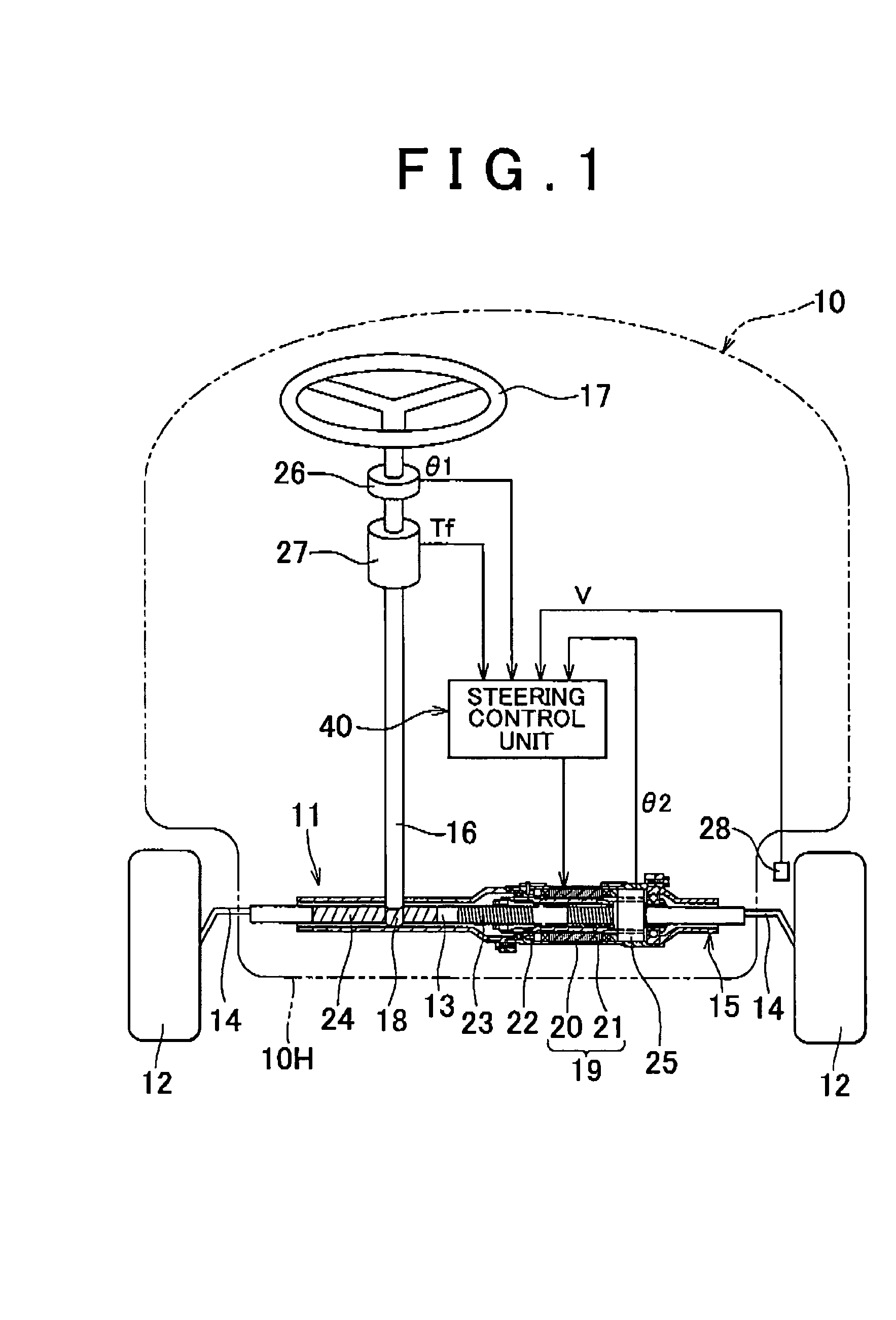
[0025]Hereinafter, the invention will be described with reference to FIG. 1 to FIG. 5. FIG. 1 shows a vehicle 10 that includes an electric power steering apparatus 11. The electric power steering apparatus 11 includes an inter-steered wheel shaft 13 that extends in the lateral direction of the vehicle 10, and the inter-steered wheel shaft 13 passes through a cylindrical housing 15 that is fixed to a vehicle body 10H. The respective ends of the inter-steered wheel shaft 13 are connected to steered wheels 12 via tie-rods 14.

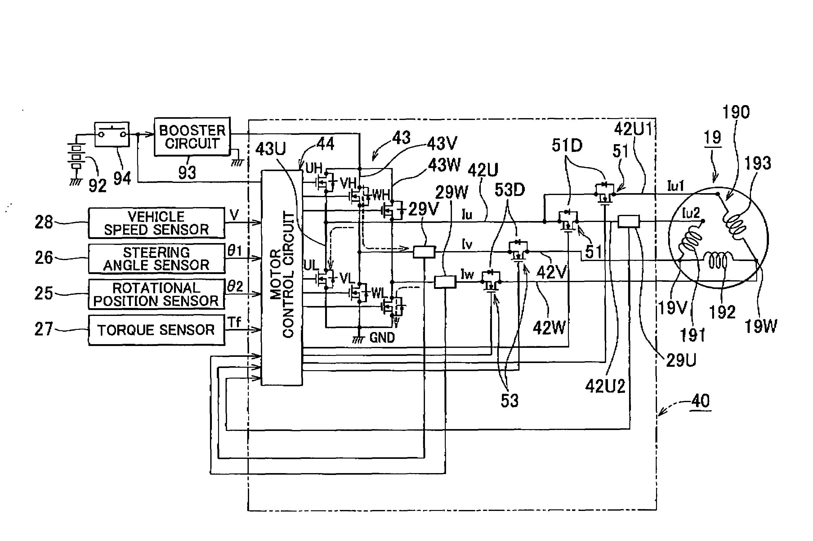
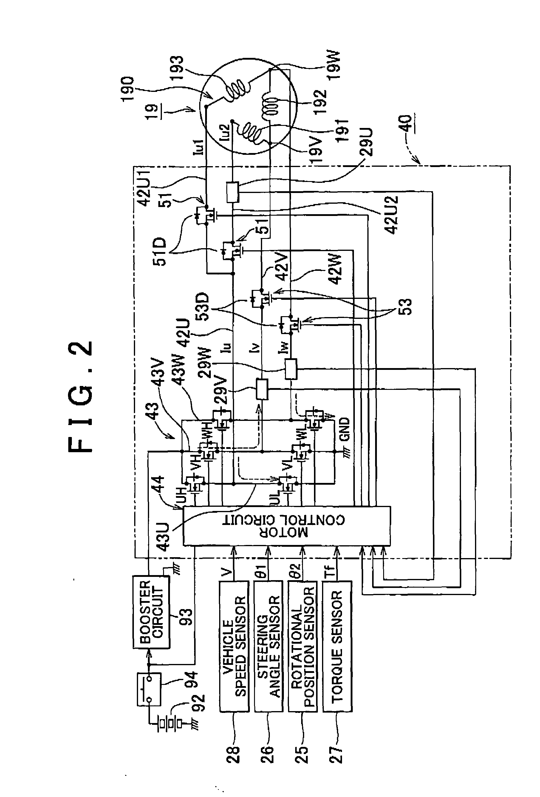
[0026]The electric power steering apparatus 11 includes a three-phase alternating-current motor 19 (hereinafter, referred to as “motor 19”) that serves as a drive source. A stator 20 of the motor 19 is fixed in the cylindrical housing 15, and the inter-steered wheel shaft 13 passes through a hollow portion of a rotor 21 of the motor 19. A ball nut 22 that is fixed to the inner face of the rotor 21 is screwed to a ball screw portion 23 that is formed in the outer fa...

second embodiment

[0055]The configuration according to the invention is shown in FIG. 6. In this configuration, each of the two feed lines 42V and 42W and the first branch feed line 42U1 in the motor drive circuit 43 is provided with one phase-open mechanical switch 59. When the ignition switch 94 is on, the mechanical switches 59 are supplied with the voltage from the motor control circuit 44 and kept on. Thus, it is possible to supply electric currents to the feed lines 42V and 42W and the first branch feed line 42U1 as well as to the second branch feed line 52U2 that is not provided with the mechanical switch 59. Also, when the ignition switch 94 is turned off, the mechanical switches 59 are turned off, and flows of electric currents are shut off in both directions.

[0056]When an abnormality occurs, even if the ignition switch 94 is on, the voltage from the motor control circuit 44 is no longer supplied to the mechanical switches 59, and all the mechanical switches 59 are turned off.

[0057]If all th...


PUM


Abstract

In a steering control unit, a U-phase feed line branches into paired branch feed lines, phase-open MOSFETs are provided in middle portions of the branch feed lines, phase-open MOSFETs are provided in middle portions of a V-phase feed line and a W-phase feed line, and the phase-open MOSFETs are arranged in such a manner that parasitic diodes are in the same orientation with respect to a motor. When an abnormality occurs, all the phase-open MOSFETs are turned off. Then, a closed circuit, which includes phase coils and through which electric currents flow, is no longer present.

Description

INCORPORATION BY REFERENCE[0001]The disclosure of Japanese Patent Application No. 2008-247137 filed on Sep. 26, 2008 including the specification, drawings and abstract is incorporated herein by reference in its entirety.BACKGROUND OF THE INVENTION[0002]1. Field of the Invention[0003]The invention relates to an electric power steering apparatus.[0004]2. Description of the Related Art[0005]In an electric power steering apparatus, if an alternating-current motor for steering assist cannot be driven due to an abnormality, the alternating-current motor is rotated in accordance with a steering operation performed on a steering wheel. In this case, the alternating-current motor serves as an electric power generator, and, for example, a battery of a vehicle is charged with the electric power generated by the alternating-current motor. In this case, the steering resistance includes, in addition to the friction resistance at a movable portion, the resistance for generating electric power by c...

Claims


Application Information

Patent Timeline
IPC IPC(8): H02H7/09B62D5/04B62D6/00B62D101/00B62D113/00B62D119/00H02P6/06H02P6/08H02P6/12H02P6/28H02P29/00H02P29/40
CPCB62D5/0484Y10S388/903Y02T10/7258B62D5/0487Y02T10/72
Inventor SHIBATA, YOSHIYUKI
Owner JTEKT CORP
Why Eureka
Try Eureka