Fiber optic coupler with variable coupling ratio and manufacturing method thereof

Inactive Publication Date: 2010-04-01
FENG CHIA UNIVERSITY
View PDF2 Cites 6 Cited by
  • Summary
  • Abstract
  • Description
  • Claims
  • Application Information

AI Technical Summary

Benefits of technology

[0008]Therefore it is a primary object of the present invention to provide a fiber optic coupler with variable coupling ratio and a manufacturing method thereof that make the manufacturing of the fiber optic coupler with variable coupling ratio easy and simple for convenience of pro

Problems solved by technology

The bottleneck of the technique

Method used


Image

  • Fiber optic coupler with variable coupling ratio and manufacturing method thereof
  • Fiber optic coupler with variable coupling ratio and manufacturing method thereof
  • Fiber optic coupler with variable coupling ratio and manufacturing method thereof

Examples


Example

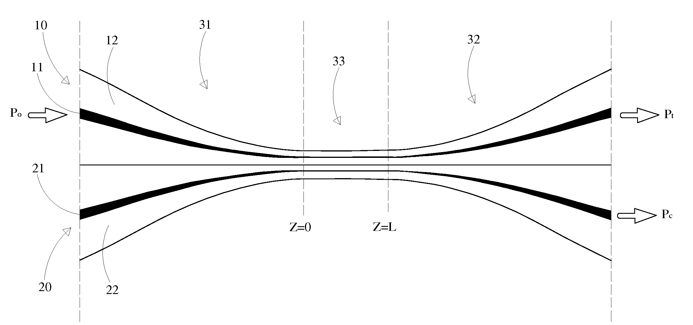
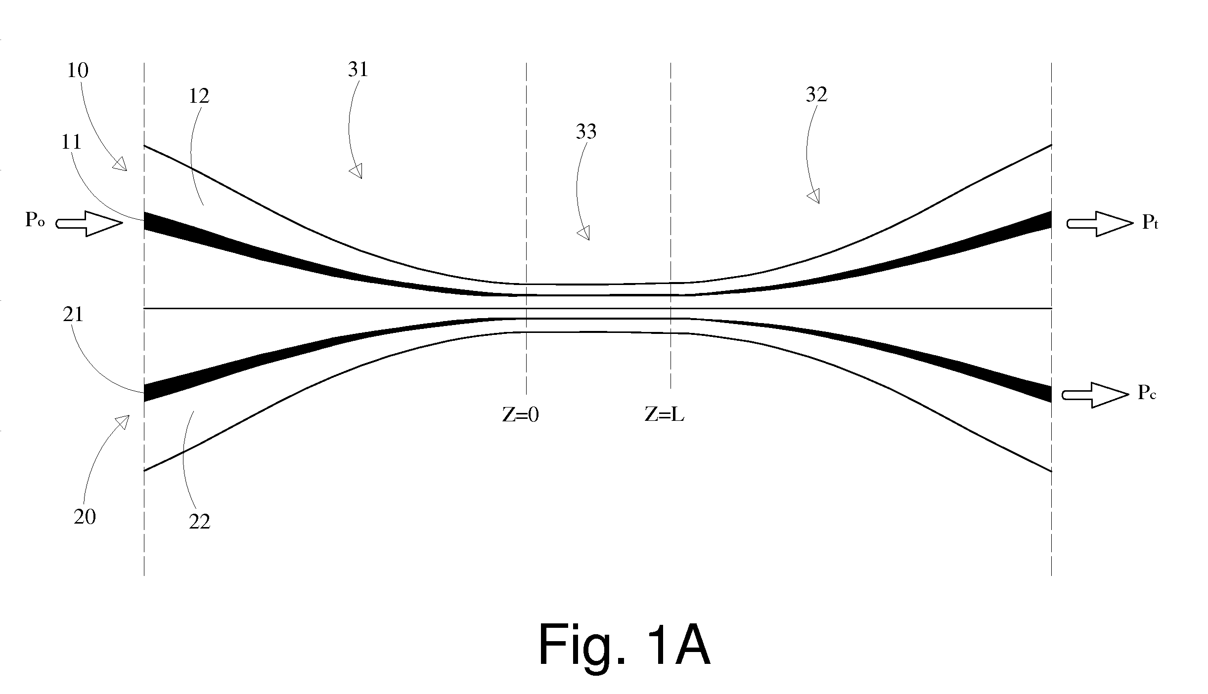
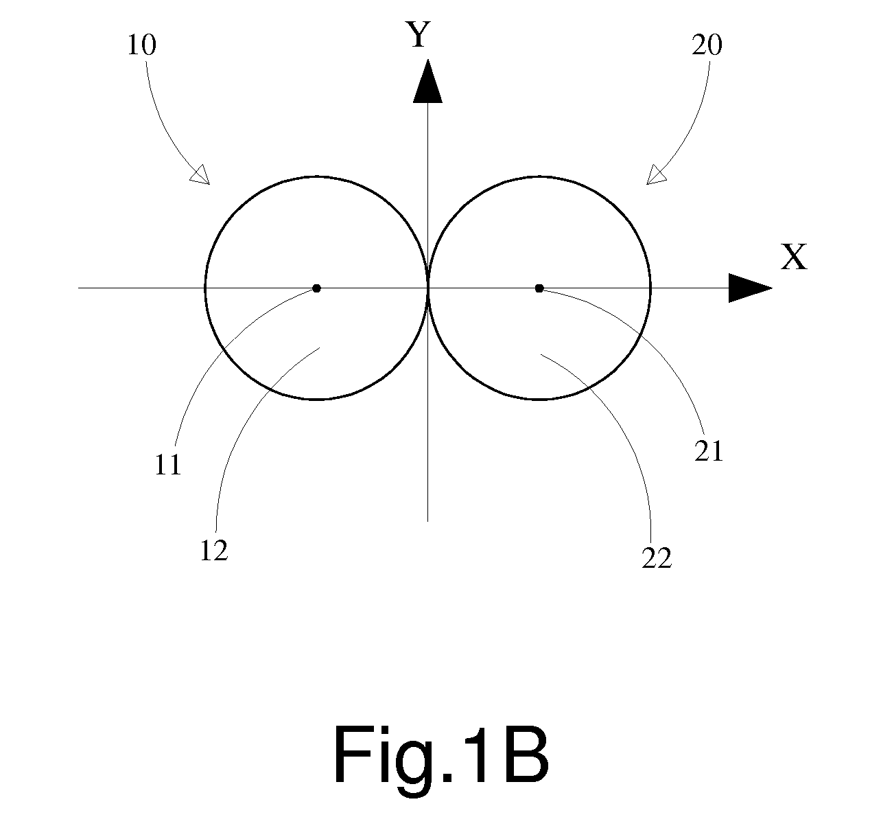
[0022]Refer from FIG. 1A to FIG. 2, a fiber optic coupler with variable coupling ratio according to the present invention consists of a first optical fiber 10, a second optical fiber 20 and a fiber loop 30. The first optical fiber 10 and the second optical fiber 20 that form an optical fiber set are single-core single-mode fibers, respectively having a core 11, 21 on an inner layer and a cladding 12, 22 on an outer layer. The claddings 12, 22 are enclosed by a protective sheath (not shown in figure) and have part of longitudinal connection portion (fusion portion). The connection portion is divided into three regions—a down taper region 31, a coupling region 33 and an upper taper region 32. The fiber loop 30 is formed by bending of the connection portion of the first optical fiber 10 as well as the connection portion of the second optical fiber 20. Thus the fiber loop 30 formed by the connection portion includes the coupling region 33, the down taper region 31 and upper taper region...


PUM


Abstract

A fiber loop formed by bending of a connection section between the first fiber and the second fiber includes a coupling region and an upper taper region as well as a down taper region arranged symmetrically on two sides of the coupling region. Then the fiber optic splitter with the fiber loop is assembled with a splitting ratio modulation mechanism. Thus the manufacturing of the fiber optic power splitter with variable splitting ratio is simplified and this favors production and applications of the device. Moreover, the splitting and modulation quality of the splitter are stable and are controlled precisely. Thus the economic benefits of the device in manufacturing, operation quality and product competitiveness are all improved.

Description

BACKGROUND OF THE INVENTION[0001]1. Field of Invention[0002]The present invention relates to an optical beam splitter, especially to a fiber optic coupler with variable coupling ratio and a manufacturing method thereof.[0003]2. Description of Related Art[0004]A fiber optic coupler transfers optical signals from one medium such as an optical fiber to other ends so that signals from an input fiber can appear at more outputs. That means it can distribute the optical signal (power) from one fiber among two or more fibers. Thus the fiber optic coupler is applied to signal / data transmission systems such as digital subscriber line system, local area networks, and cable TV networks. However, the output ratio of conventional couplers is fixed so that its development and application are limited. Thus a fiber optic coupler with variable coupling ratio is further developed, as shown in U.S. Pat. No. 4,493,528 and U.S. Pat. No. 4,763,977.[0005]Refer to U.S. Pat. No. 4,493,528, two fiber optic st...

Claims


Application Information

Patent Timeline
IPC IPC(8): G02B6/26
CPCG02B6/3594G02B6/2835
Inventor WU, CHENG-WEN
Owner FENG CHIA UNIVERSITY
Why Eureka
Try Eureka