Method and device for controlling heaters of conveying and distribution system

A technology of heater and control unit, which is applied in the direction of electric control of muffler, exhaust device, exhaust treatment device, etc., which can solve the problems of cumbersome design of circuit boards, overshooting, etc., and achieve the effect of low cost

Active Publication Date: 2016-05-04
ROBERT BOSCH GMBH
View PDF7 Cites 2 Cited by
  • Summary
  • Abstract
  • Description
  • Claims
  • Application Information

AI Technical Summary

Problems solved by technology

[0006] If ohmic heaters are increasingly used in the future instead of previously used heaters with PTC elements, then the existing control of the heaters will have another disadvantage, because the current of the ohmic heaters is constant at a constant voltage. is nearly c

Method used


Image

  • Method and device for controlling heaters of conveying and distribution system
  • Method and device for controlling heaters of conveying and distribution system
  • Method and device for controlling heaters of conveying and distribution system

Examples


Embodiment Construction

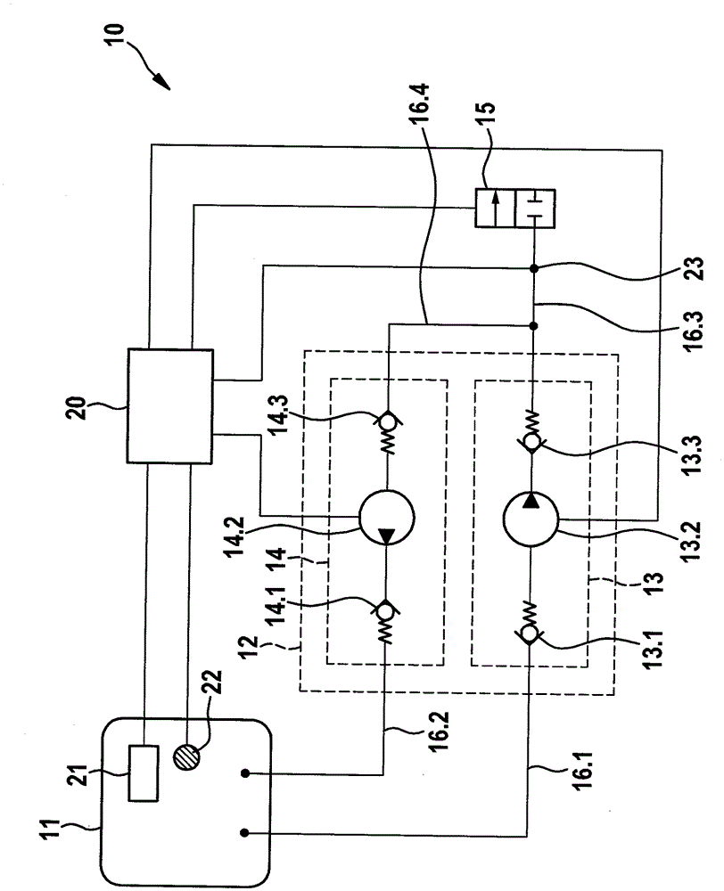
[0028] figure 1 A possible embodiment schematically shows a delivery and distribution system 10 for a reducing agent for the selective catalytic reduction of exhaust gases, which, in one design variant, has a Feedback pump 14.2, the figure thus shows a technical field in which the invention can be applied.

[0029] The delivery and dosing system 10 contains a reducing agent tank 11 , a delivery unit 12 , a pressure line system with at least one pressure line 16 . 3 , a dosing unit 15 , the necessary sensors and an electronic control unit 20 .

[0030] The conveying unit 12 is composed of an input system 13 and a feedback system 14 . In this case, the supply system 13 consists of a delivery pump 13.2, a first supply valve 13.1 and a first output valve 13.3. The delivery pump 13.2 is connected on the inlet side to the reducing agent tank 11 via a first inlet valve 13.1 and an inlet line 16.1. On the output side, the delivery pump 13.2 is connected to the dosing unit 15 via a ...


PUM


Abstract

The invention relates to a method and device for a conveying and distribution system for thawing a reducing agent for selective catalytic reduction of exhaust gas of an internal combustion engine. Here, a maximum available electrical power is fully or in part distributed to the designated heaters during a warm-up period according to a time-variable priority specification.Pulse-width modulation of the heaters is carried out such that output pulses do not overlap or overlap only for the smallest possible time. A heating strategy for the conveying and distribution system is determined by energy balance for the reducing agent. The method and the device lead to increased thawing amount during the thawing time and lead to an optimized thawing time of the conveying and metering system in short breaks, so that the work ready state of the conveying and distribution system can be achieved quickly and sustainably.

Description

technical field [0001] The invention relates to a method for controlling at least two heaters of a delivery and distribution system for reducing agent for the selective catalytic reduction of the exhaust gases of an internal combustion engine with at least one heater for controlling Control unit for at least two heaters. [0002] The invention also relates to a control unit for controlling at least two heaters of a delivery and distribution system of a reducing agent for the selective catalytic reduction of exhaust gases of an internal combustion engine. Background technique [0003] In order to reduce pollutant emissions, it is known to dispense liquids, in particular in the form of reducing agents, into the exhaust gas ducts of internal combustion engines. Thus, for example, the nitrogen oxide emissions of the internal combustion engine can be reduced by means of selective catalytic reduction (SCR) by means of exhaust gas aftertreatment. Here, a predetermined amount of s...

Claims


Application Information

Patent Timeline
IPC IPC(8): F01N9/00F01N3/10
CPCF01N3/208F01N2610/02F01N2610/10F01N2610/105F01N2900/104F01N2900/12F01N2900/1811F01N2900/1821F01N2900/1822Y02T10/12
Inventor T.法尔T.布勒斯特尔S.拉策尔M.蔡诺伊克斯
Owner ROBERT BOSCH GMBH
Why Eureka
Try Eureka