
Variable geometry turbocharger

a variable geometry, turbocharger technology, applied in the direction of machines/engines, mechanical apparatus, liquid fuel engines, etc., can solve the problems of prior art variable geometry turbochargers that are generally unreliable and prone to mechanical failure, prior art variable geometry turbochargers that fail to operate at peak efficiency,

Inactive Publication Date: 2010-04-01
KANSAS STATE UNIV RES FOUND
View PDF8 Cites 27 Cited by
  • Summary
  • Abstract
  • Description
  • Claims
  • Application Information

AI Technical Summary

Problems solved by technology

While the prior art features permit turbocharger matching, prior art turbochargers suffer from various limitations.
For instance, prior art variable geometry turbochargers are generally unreliable and prone to mechanical failure.
Furthermore, prior art turbochargers include compressors that have a narrow operating range between surge and choke conditions, particularly under off-design operating conditions.
The prior art turbochargers also fail to operate at peak efficiency over a range of engine load or engine speed.

Method used


Image

  • Variable geometry turbocharger
  • Variable geometry turbocharger
  • Variable geometry turbocharger

Examples


Embodiment Construction

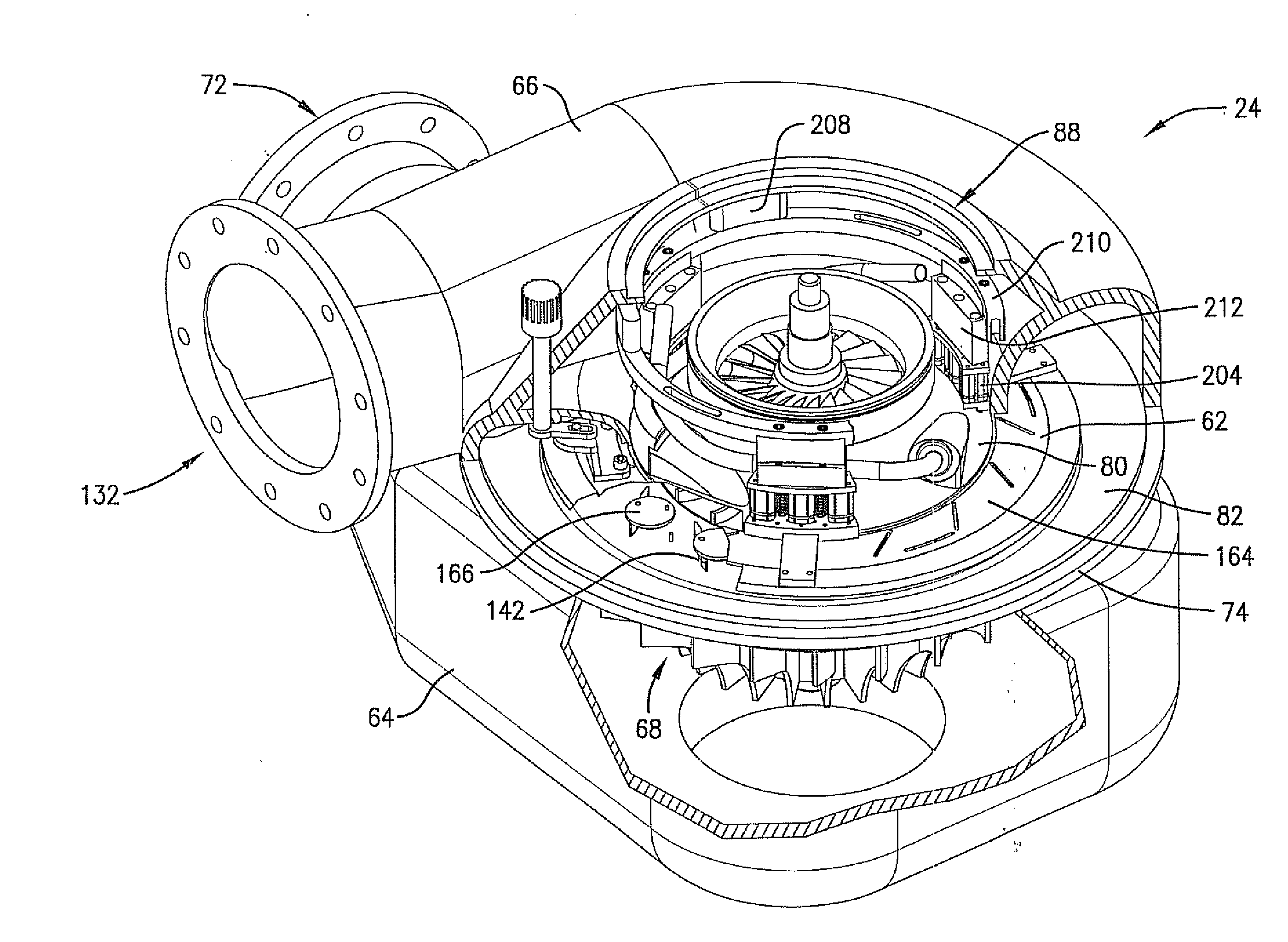
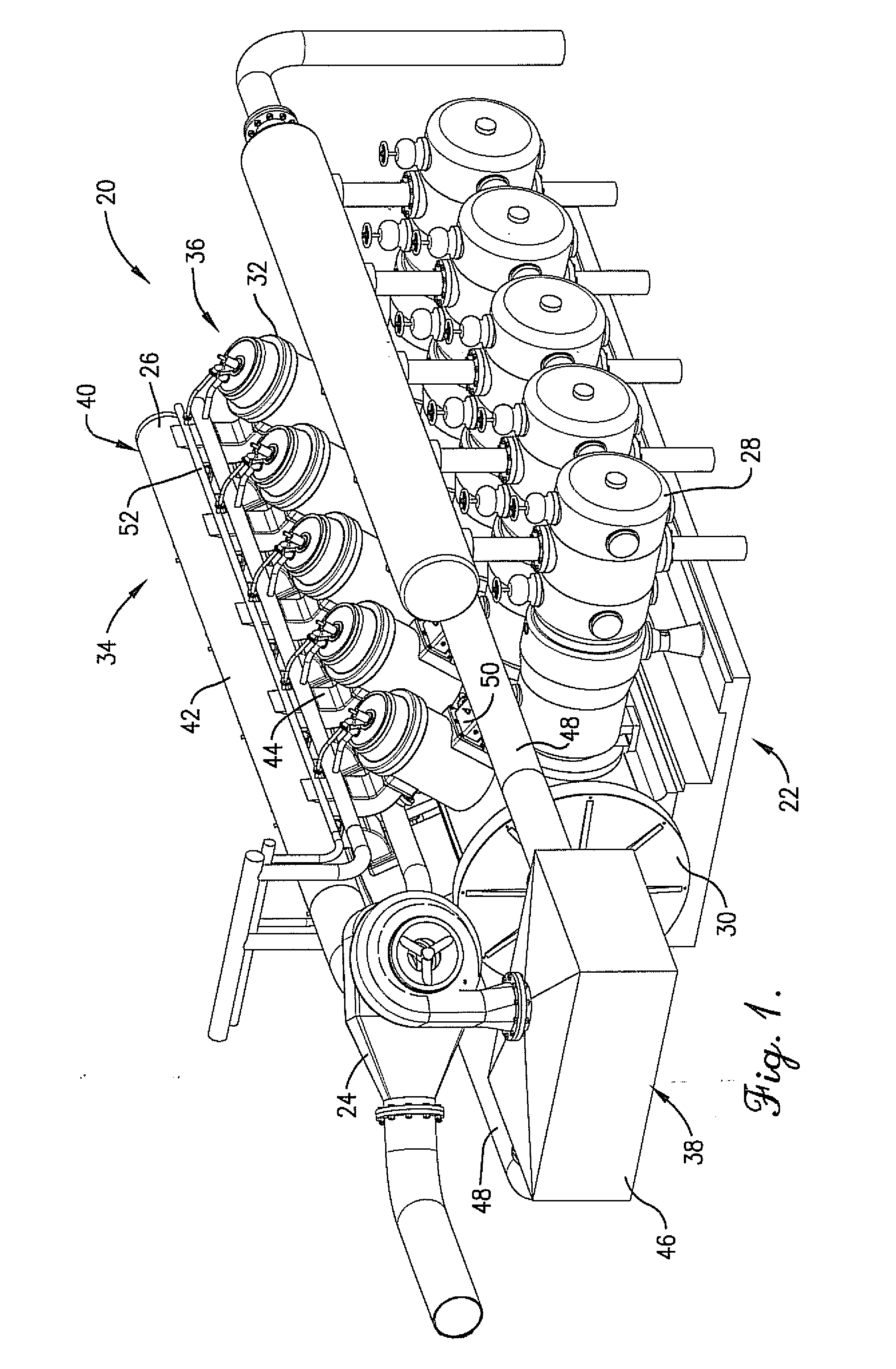
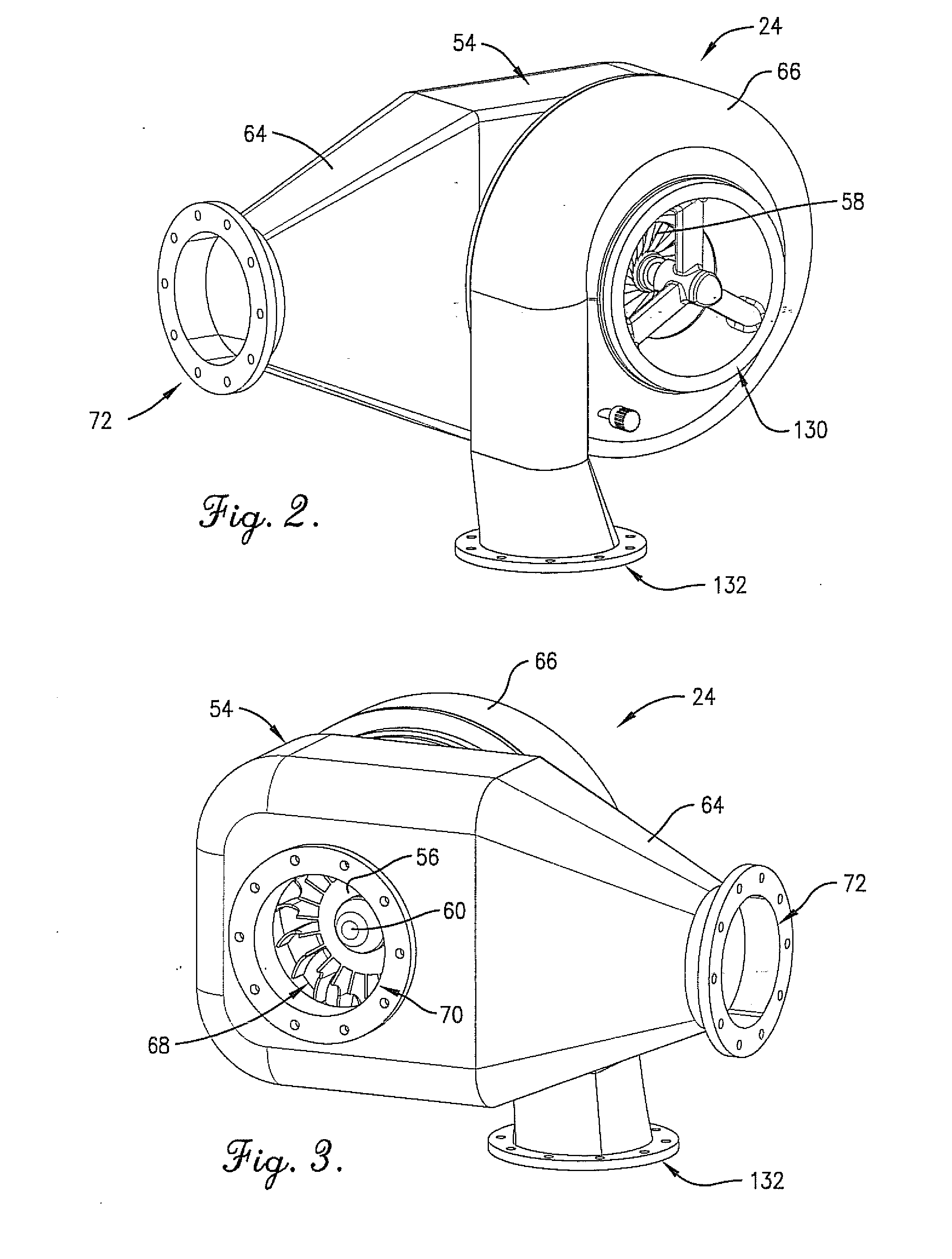
[0027]Turning initially to FIG. 1, a turbocharged engine 20 is operable to compress and transmit natural gas along a natural gas transmission line (not shown). The turbocharged engine 20 is particularly suited to operate efficiently while producing a minimal amount of harmful gas emissions, such as NOX emissions, from engine operation. The illustrated turbocharged engine 20 is preferably used for gas transmission, but the principles of the present invention are applicable for other internal combustion engine applications, such as marine power, electricity generation, construction equipment, over-the-road vehicles, and other industrial power applications, that require an efficient and low-emission internal combustion engine. The turbocharged engine 20 broadly includes an integral gas engine-compressor 22 and a turbocharger assembly 24.

[0028]The integral gas engine-compressor 22 is fluidly coupled to the natural gas transmission line to compress and transmit natural gas. The illustrat...


PUM


Abstract

A turbocharged engine includes an internal combustion engine and a variable geometry turbocharger. The turbocharger is adjustable to operate efficiently under various engine operating and environmental conditions. The turbocharger includes a turbine and compressor, with the compressor including a compressor housing, an impeller rotatably mounted in the housing, and an adjustable diffuser vane assembly. The diffuser vane assembly includes a plurality of pivotal diffuser vanes spaced about the impeller and a vane rotation drive that interconnects the vanes and permits simultaneous adjustment of the diffuser vanes to improve the efficiency and operating range of the turbocharger. The diffuser vane assembly also includes a vane locking drive operable to engage the pivotal vanes and prevent vane movement during turbocharger operation.

Description

CROSS REFERENCE TO RELATED APPLICATION[0001]This application is being filed contemporaneously with application for U.S. patent Ser. No. ______, entitled TURBOCHARGER BOOSTER SYSTEM, and application for U.S. patent Ser. No. ______, entitled ACTIVE AIR CONTROL, both of which are hereby incorporated in their entirety by reference herein.BACKGROUND[0002]1. Field[0003]The present invention relates generally to turbochargers. More specifically, embodiments of the present invention concern a variable geometry turbocharger with adjustable vanes.[0004]2. Discussion of Prior Art[0005]Turbochargers are commonly used to improve the performance of reciprocating internal combustion engines. Prior art turbochargers include a turbine, which is powered by energy available from engine exhaust, and a compressor driven by the turbine to provide a compressed charge of intake air to the engine. It is well known for turbochargers to have operating, characteristics matched with a corresponding engine so th...

Claims


Application Information

Patent Timeline
IPC IPC(8): F02B37/24
CPCF02B37/24F04D29/462Y02T10/144F05B2260/506F05B2220/40F05D2250/52Y02T10/12
Inventor CHAPMAN, KIRBYHONNEGGER, UELI
Owner KANSAS STATE UNIV RES FOUND
Learn More