Vacuum-Stabilized Ablation System

Active Publication Date: 2010-04-01
ST JUDE MEDICAL ATRIAL FIBRILLATION DIV
26 Cites 30 Cited by

AI-Extracted Technical Summary

Problems solved by technology

These conditions can decrease cardiac output and reduce tissue perfusion to the detriment of a subject.
Establishing adequate contact with the target tissue to successfully perform a PVI (i.e., create a continuous lesion or set of connected lesions around one or more pulmonary veins)...

Method used

[0046]Referring now to FIG. 9, in one embodiment, the ablating element 20 includes an anti-occlusion element 40 on the second surface 26 that prevents the tissue from being drawn into the ports 30 and occluding the ports 30 resulting in loss of tissue capture. In embodiments having two or more ports, occluding one port may result in loss of contact at the other ports. Thus, it is useful to provide a mechanism to reduce or eliminate the incidence of port occlusion. As shown in FIG. 9, the anti-occlusion element 40 may be a series of grooves 46 formed on the second surface 26 of the ablating element 20. The grooves 46 are depressions, textures or indentations formed or etched on the second surface 26 that communicate with the port 30. In other words, the grooves 46 connect to or join an outer edge 35 of the at least one port 30. In one embodiment, the anti-occlusion element 40 may include a series of grooves 46 expanding radially outwardly from the outer edge 35 of the port 30 to the rim 32. In another embodiment, the anti-occlusion element 40 may include a series of ridges or protuberances (not illustrated) on the second surface 26. The ridges or protuberances may be raised elements arranged in various patterns to give the second surface 26 texture or roughness.
[0051]In a further embodiment, to assist in orienting and locating, the ablation catheter 10 includes one or more electrodes 48 disposed on the distal portion 16 of the elongate body 12 (see FIG. 3, for example). The electrodes 48 may advantageously be used to orient the ablation catheter 10 to ensure that the second surface 26 of the ablating element 20 is facing or oriented towards the tissue desired to be ablated. In a particular configuration, the electrodes 48 may be unipolar or bipolar electrogram (EGM) electrodes adapted to measure electrical activity present on a surface of the tissue. For example, in one embodiment, a pair of bipolar electrodes 48 is disposed on an outer surface of the housing 22, the electrodes in the pair being disposed on opposite sides of the ablating element 20, as shown in FIG. 6, for example. In another embodiment, two pairs of bipolar electrodes 48 are used, as shown in FIG. 3, for example. The electrodes 48 are disposed on opposite sides of the ablating element 20 in a lateral direction generally perpendicular to a central axis of the elongate body 12 of the ablation catheter 10. Alternatively, or in addition to the foregoing, a bipolar pair of electrodes 48 may be disposed on opposite sides of the ablating element 20 in a lateral direction generally parallel to a central axis of the catheter body. In one embodiment, a side portion of the electrodes 48 (i.e., a portion that is exposed on the side of the housing 22, as shown in FIG. 3), is covered in a biocompatible material to prevent pacing and/or sensing of tissue that may contact the side portion of the electrodes 48. To ensure that the second surface 26 of the ablating element 20 is properly oriented towards the target tissue, the top portion of the electrodes 48 (i.e., the portion that is co-planar with the rim 32 of the second surface 26), emits and/or senses the pacing and/or sensing signals.
[0057]Referring to FIGS. 2A, 3 and 10, the elongate body 12 of the ablation cathe...

Benefits of technology

[0011]An object of the present invention is to provide ablati...

Abstract

Cardiac ablation systems include vacuum-stabilized, irrigated ablation devices that have ablating elements capable of providing regions of relatively low pressure to maintain the ablating element in a stable position relative to the tissue, or minimize relative movement of the ablating element relative to the tissue. The ablation elements have integrated structures for vacuum-stabilization. The devices also include one or more electrodes for both orienting the ablating element as well as for diagnostic purposes.

Application Domain

ElectrocardiographyInternal electrodes +3

Technology Topic

Biomedical engineeringCardiac Ablation +3

Image

  • Vacuum-Stabilized Ablation System
  • Vacuum-Stabilized Ablation System
  • Vacuum-Stabilized Ablation System

Examples

  • Experimental program(1)

Example

EXAMPLE
[0069]The following example of methods of use is provided as additional disclosure although the specifics should be generally appreciated by those of skill in the art to which this disclosure pertains.
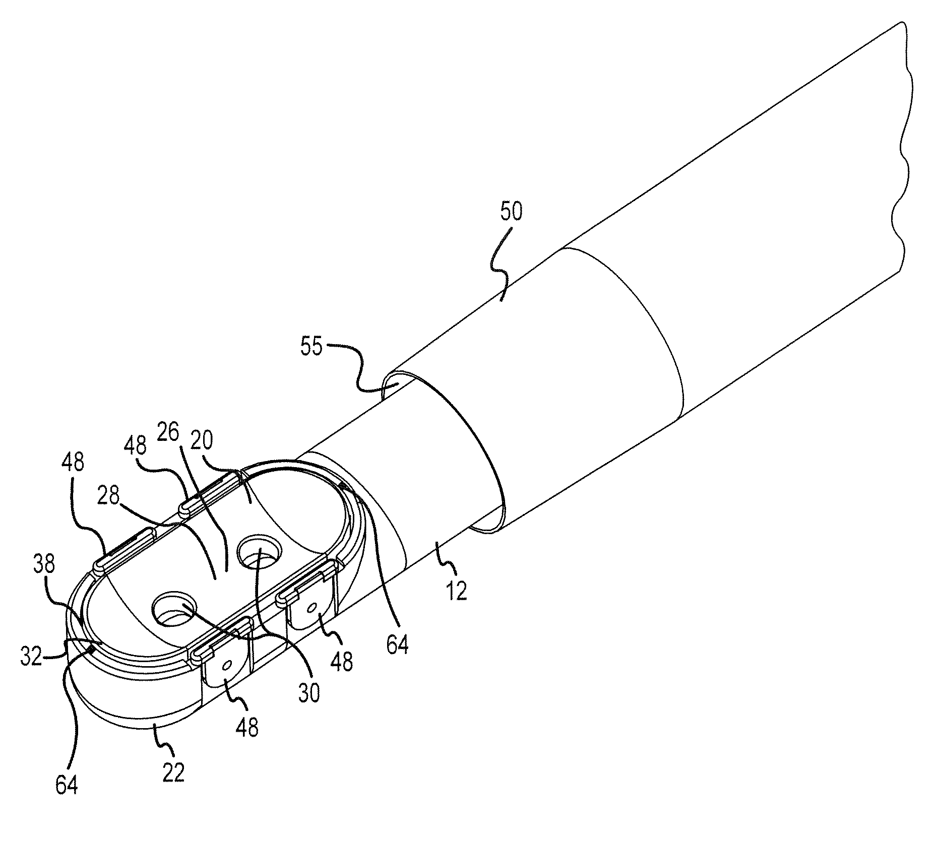
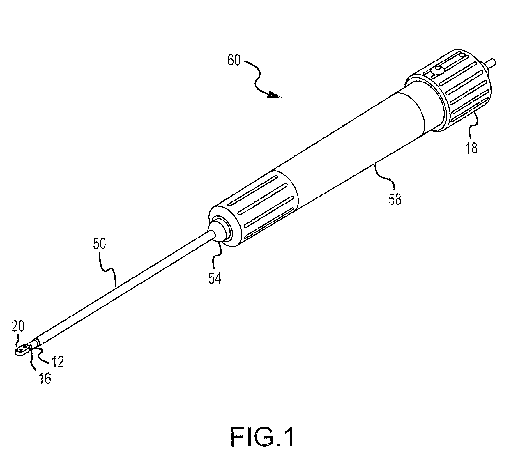
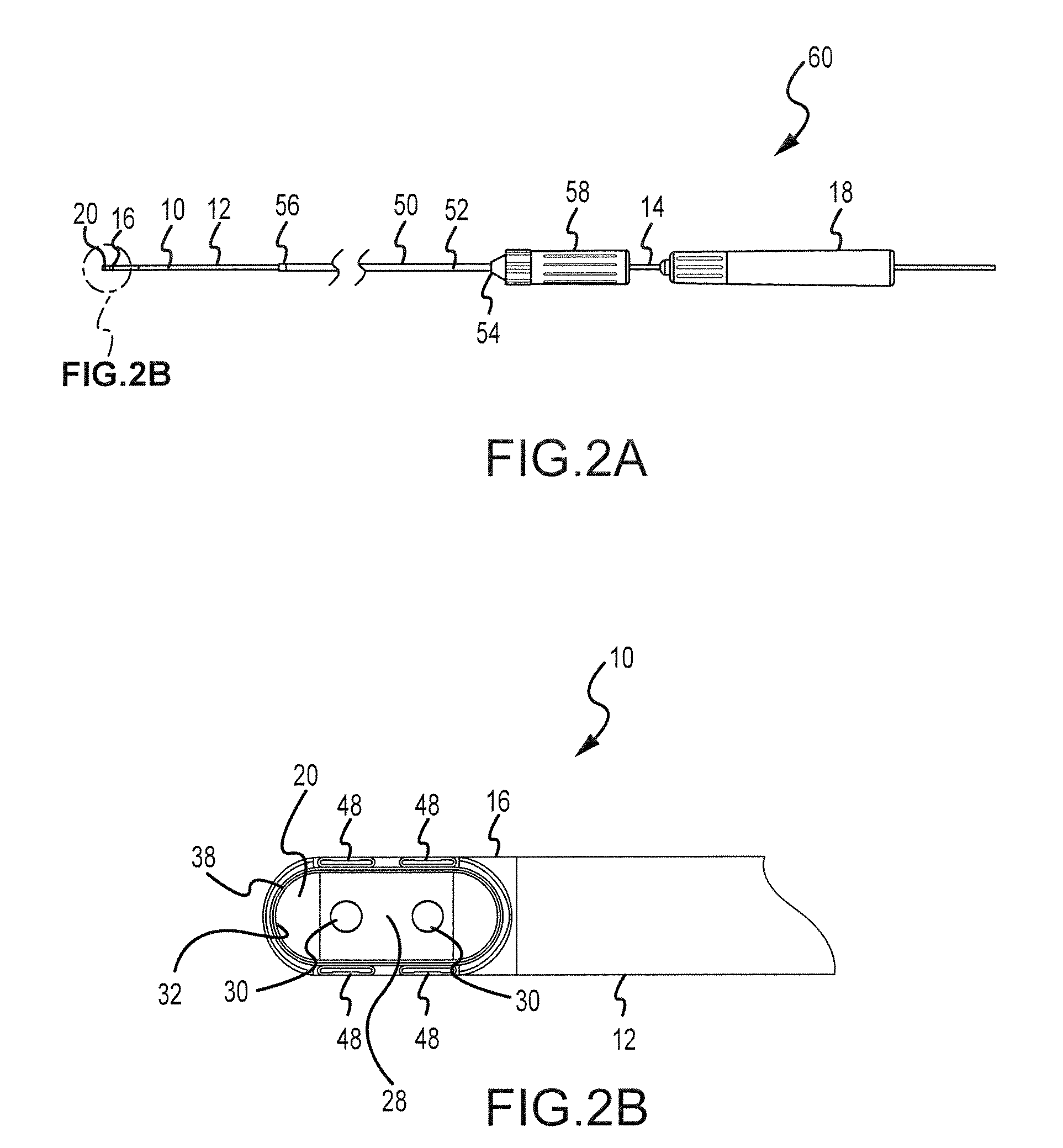
[0070]A method of ablating epicardial tissue includes providing a guiding catheter, the guiding catheter comprising a body and a continuous lumen extending through the body, a distal end, a proximal portion, and a first handle coupled to the proximal end, and providing an ablation catheter slideably disposed within the lumen of the guiding catheter. The ablation catheter includes an elongate body defining a lumen therethrough, a proximal end, a second handle coupled to the proximal end, a distal portion, and at least one ablating element coupled to the distal portion. The at least one ablating element includes a first surface and a second surface, and the second surface includes a base portion, at least one port and a rim. The ablation catheter further includes at least one cardiac electrode coupled to the distal portion of the elongate body, a suction lumen coupled to the at least one port at a distal end thereof and a source of varying pressure at a proximal end thereof. Additionally, the ablation catheter includes an irrigation channel surrounding at least a portion of the rim, and an irrigation lumen fluidly coupled to the irrigation channel at a distal end thereof and a source of irrigation fluid at a proximal end thereof.
[0071]The method further includes inserting the guiding catheter and the ablation catheter into a body cavity, advancing the guiding catheter and the ablation catheter to a location near an epicardial tissue, and advancing the ablation catheter through the guiding catheter until the ablating element exits the distal end of the guiding catheter. The step of inserting a guiding catheter and the ablation catheter into a body cavity may include inserting the guiding catheter into the pericardial space via a percutaneous subxiphoid approach. The ablating element is oriented to place the second surface in contact with or facing an epicardial tissue, and the source of varying pressure is activated to maintain the ablating element in a stable position relative to the tissue, or minimize relative movement of the ablating element relative to the tissue. A fluid is delivered through the irrigation lumen and the irrigation channel to irrigate the tissue, and the ablating element is activated to ablate the tissue. To orient the ablating element in relation to the tissue, the second handle is manipulated to cause axial rotation of the distal portion of the ablation catheter relative to a longitudinal axis of the elongate ablation catheter body, and the at least one pair of electrodes sense electrical activity on the tissue to indicate when the ablating element is oriented towards the epicardial tissue. The at least one pair of electrodes may measure an impedance after ablating the tissue to confirm that an effective lesion has been created.
[0072]The recitation of one or more embodiments discussed or described herein does not imply that other embodiments are not useful and is not intended to exclude other embodiments from the scope of the invention and no disclaimer of other embodiments should be inferred from the discussion of a certain embodiment or a figure showing a certain embodiment.
[0073]Although multiple embodiments have been described above with a certain degree of particularity, those skilled in the art could make numerous alterations to the disclosed embodiments without departing from the teaching of this disclosure. All directional references (e.g., upper, lower, upward, downward, left, right, leftward, rightward, top, bottom, above, below, vertical, horizontal, clockwise, and counterclockwise) are only used for identification purposes to aid the reader's understanding of the disclosure and do not create limitations, particularly as to the position, orientation, or use of the subject matter herein described, depicted and claimed. Joinder references (e.g., attached, coupled, connected, and the like) are to be construed broadly and may include intermediate members between a connection of elements and relative movement between elements. As such, joinder references do not necessarily infer that two elements are directly connected and in fixed relation to each other. It is intended that all matter contained in the above description or shown in the accompanying drawings shall be interpreted as illustrative only and not limiting. Changes in detail or structure may be made without departing from the teaching of this disclosure as defined in the appended claims.

PUM

no PUM

Description & Claims & Application Information

We can also present the details of the Description, Claims and Application information to help users get a comprehensive understanding of the technical details of the patent, such as background art, summary of invention, brief description of drawings, description of embodiments, and other original content. On the other hand, users can also determine the specific scope of protection of the technology through the list of claims; as well as understand the changes in the life cycle of the technology with the presentation of the patent timeline. Login to view more.

Similar technology patents

Automatic pet feeder

ActiveUS20160007564A1improve stability
Owner:TONGFU MFG

Stamping equipment applied to motor rotor punching sheet production

Owner:SHENGZHOU LIDA ELECTRIC APPLIANCES FACTORY

Method for recycling manganese ion in electrolytic manganese production tail end wastewater

InactiveCN101838064AImprove stabilityReduce the number of operators
Owner:CHINESE RES ACAD OF ENVIRONMENTAL SCI

Coverage rate test processing method and device and coverage rate test server and system

ActiveCN103095518AImprove stabilityReduce the probability of failure
Owner:ALIBABA GRP HLDG LTD

Classification and recommendation of technical efficacy words

Why Eureka
Try Eureka