Speed control device for vehicle

a technology of speed control device and vehicle, which is applied in the direction of braking system, process and machine control, instruments, etc., can solve problems such as discomfort for drivers

Active Publication Date: 2010-04-01
ADVICS CO LTD +1
View PDF6 Cites 20 Cited by
  • Summary
  • Abstract
  • Description
  • Claims
  • Application Information

AI Technical Summary

Benefits of technology

[0006]According to an aspect of the present invention, a speed control device for a vehicle includes a vehicle speed obtaining means for obtaining a speed of the vehicle, a shape obtaining means for obtaining a shape of a curve existing ahead of the vehicle, a position obtaining means for obtaining a positional relationship between the curve and the vehicle, a target vehicle speed determining means for determining a target vehicle speed in a case where the vehicle travels through the curve, on the basis of the shape of the curve and the positional relationship, a vehicle speed controlling means for controlling the speed of the vehicle on the basis of the target vehicle speed and the speed of the vehicle, and an acceleration operation quantity obtaining means for obtaining an operation quantity of an acceleration operating member, which is to be operated by a driver of the vehicle, wherein the target vehicle speed determining means includes a modification means for modifying the target vehicle speed on the basis of the operation quantity so that the target vehicle speed in a case where the operation quantity is greater than zero becomes a greater value than the target vehicle speed in a case where the operation quantity is zero.
[0007]According to another aspect of the present invention, a speed control device for a vehicle includes a vehicle speed obtaining means for obtaining a speed of the vehicle, a shape obtaining means for obtaining a shape of a curve existing ahead of the vehicle, a reference determining means for determining an appropriate vehicle speed, by which the vehicle is to appropriately travel through the curve, and a reference point, which exists on the curve and which is a point by which the speed of the vehicle is to be decreased down to the appropriate vehicle speed, on the basis of the shape of the curve, a distance obtaining means for obtaining a relative distance of a zone between the reference point and the vehicle, a target vehicle speed determining means for determining a target vehicle speed for decreasing the speed of the vehicle down to the appropriate vehicle speed on the basis of the reference point, the appropriate vehicle speed and the relative distance, a vehicle speed controlling means for controlling the speed of the vehicle on the basis of the target vehicle speed and the speed of the vehicle, and an acceleration operation quantity obtaining means for obtaining an operation quantity of an acceleration operating member, which is to be operated by a driver of the vehicle, wherein the target vehicle speed determining means includes a modification means for modifying the target vehicle speed on the basis of the operation quantity so that the target vehicle speed in a case where the operation quantity is greater than zero becomes a greater value than the target vehicle speed in a case where the operation quantity is zero.

Problems solved by technology

Generally, the driver may feel discomfort when a targeted acceleration of the vehicle is not achieved, such in a case where the vehicle is decelerated by the deceleration control contrary to a driver's intention of accelerating the vehicle.
In other words, the discomfort, which may be caused due to insufficient acceleration and the like, may be felt by the driver not only at the near side of the curve exit, but also while the vehicle travels on the curve (i.e. at any zone of the curve).

Method used


Image

  • Speed control device for vehicle
  • Speed control device for vehicle
  • Speed control device for vehicle

Examples


Embodiment Construction

[0023]An embodiment of a speed control device for a vehicle will be described below in accordance with the attached drawings.

[0024]

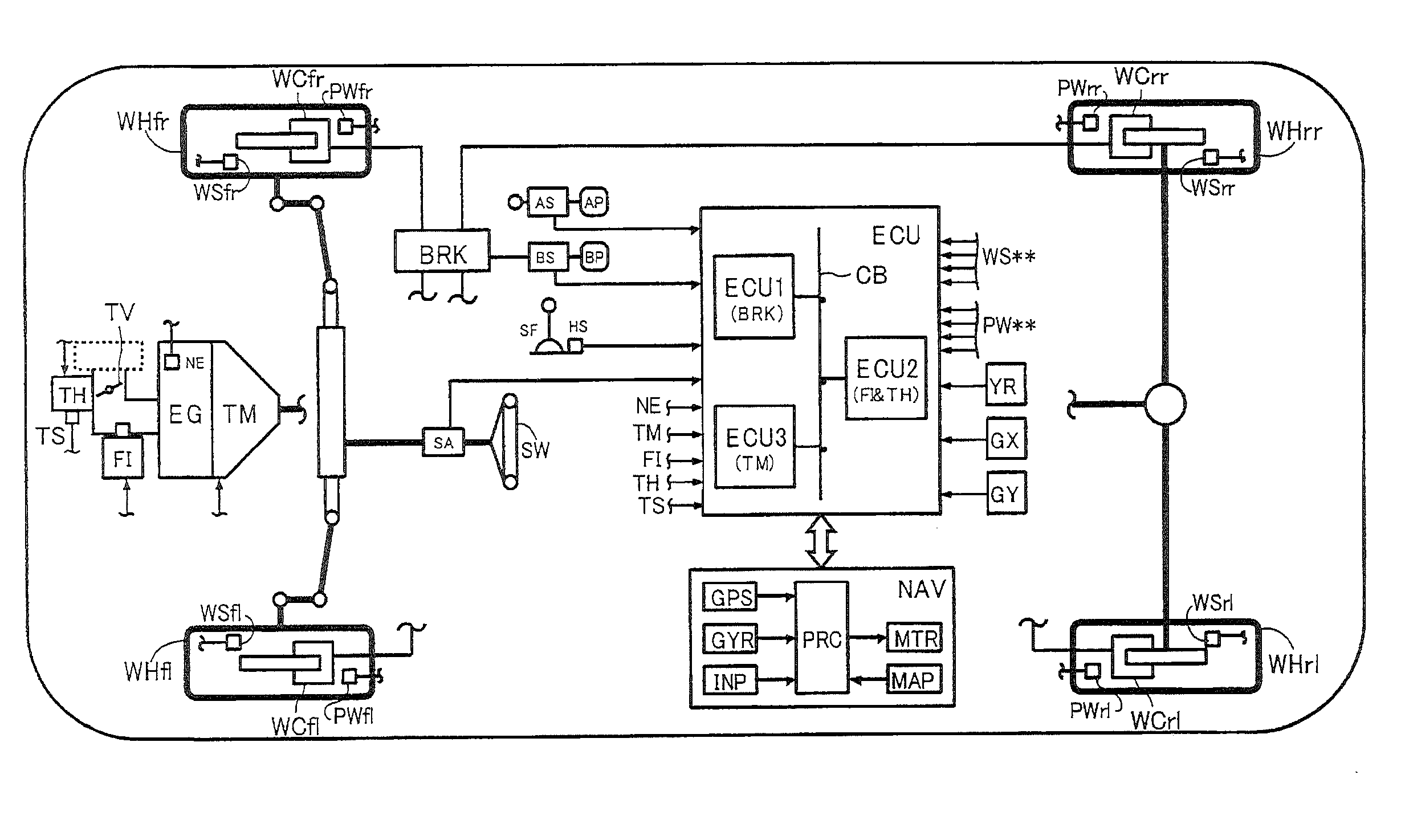
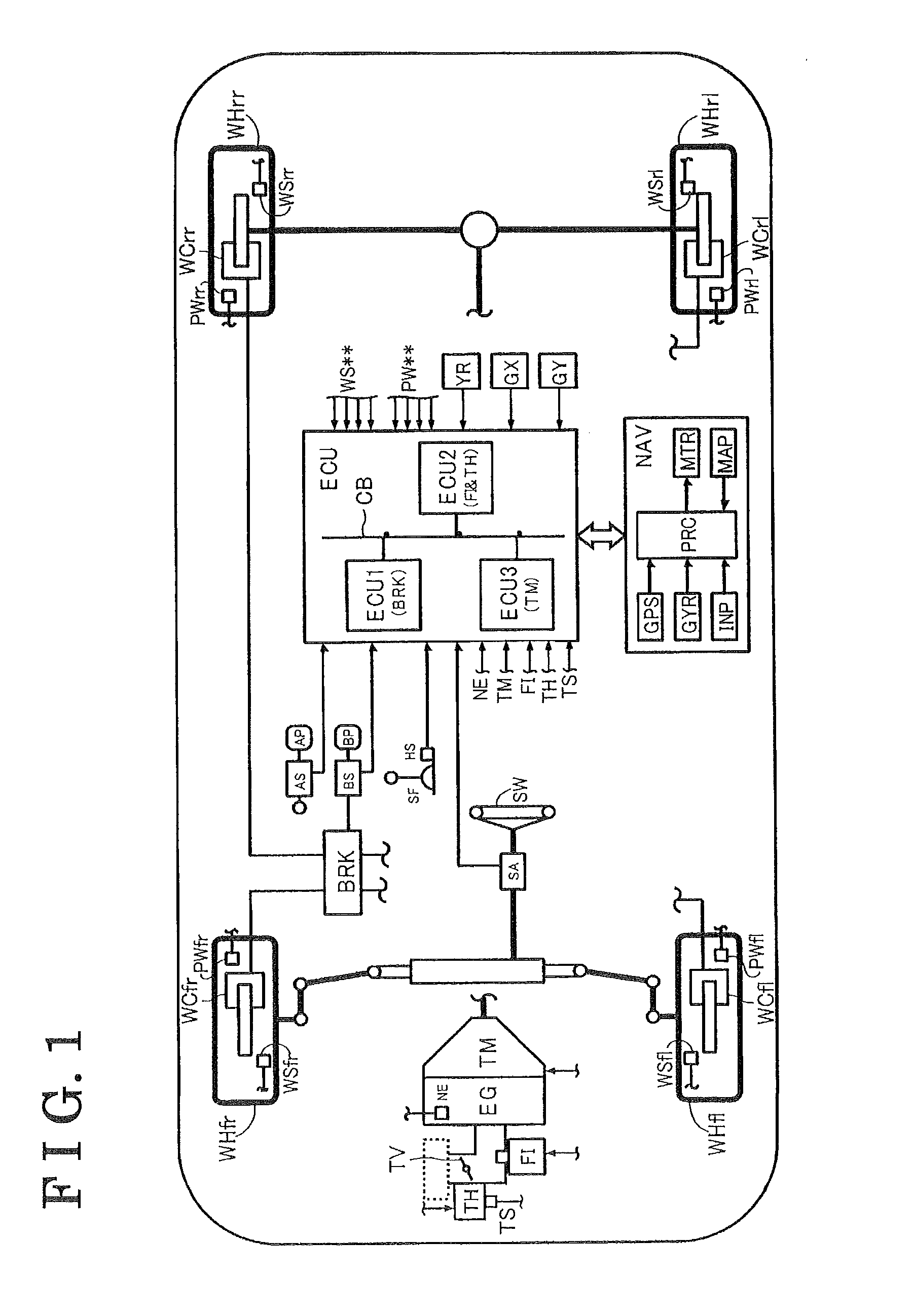
[0025]Illustrated in FIG. 1 is a schematic configuration of the vehicle to which the speed control device (which will be hereinafter referred to simply as a device) according to the embodiment is provided. The device includes an engine EG, which serves as a power source of the vehicle, an automatic transmission TM, a brake actuator BRK, an electronic control unit ECU and a navigation device NAV.

[0026]For example, an internal combustion engine is used as the engine EG. More specifically, an opening degree of a throttle valve TV is adjusted by a throttle actuator TH in response to an operation of an acceleration pedal (an acceleration operating member) AP by a driver. Accordingly, an amount of fuel proportional to an inhaled air volume, which is adjusted in response to the opening degree of the throttle valve TV, is injected by a fuel injection actuator FI...


PUM


Abstract

A speed control device for a vehicle includes a vehicle speed obtaining means obtaining a vehicle speed, a shape obtaining means obtaining a curve shape, a position obtaining means obtaining a positional relationship between a curve and the vehicle, a target vehicle speed determining means determining a target vehicle speed based on the curve shape and the positional relationship, a vehicle speed controlling means controlling the vehicle speed based on the target vehicle speed and the vehicle speed, and an acceleration operation quantity obtaining means obtaining an operation quantity of an acceleration operating member operated by a driver, wherein the target vehicle speed determining means includes a modification means modifying the target vehicle speed based on the operation quantity so that the target vehicle speed obtained when the operation variable is greater than zero becomes a greater value than the target vehicle speed obtained when the operation quantity is zero.

Description

CROSS REFERENCE TO RELATED APPLICATIONS[0001]This application is based on and claims priority under 35 U.S.C. §119 to Japanese Patent Application 2008-249568, filed on Sep. 29, 2008, the entire content of which is incorporated herein by reference.FIELD OF THE INVENTION[0002]The present invention generally relates to a speed control device for a vehicle. More specifically, the present invention pertains to a speed control device, which executes a speed control in a case where the vehicle travels through a curve.BACKGROUND[0003]Disclosed in JP2005-170152A is a deceleration control device that reduces a controlling amount (a controlling level) of a deceleration control in a case where the vehicle is determined to travel a near side of a curve exit, so that a decelerating degree of a vehicle is reduced in order to avoid a driver from feeling discomfort because of insufficient acceleration of the vehicle in the vicinity of the curve exit, which may occur when the deceleration control is ...

Claims


Application Information

Patent Timeline
Patent Type & Authority Applications(United States)
IPC IPC(8): G05D13/02B60T7/12B60W10/00B60W10/04B60W10/06B60W10/10B60W10/18B60W10/184B60W10/20B60W30/00B60W30/14
CPCB60K31/0066B60W2550/143B60W2540/10B60W30/143B60W2552/20B60W2552/30
Inventor YASUI, YOSHIYUKIKOTO, HIDEAKIKODAMA, HIROYUKIMARUYAMA, MASAKIMIYAJIMA, TAKAYUKI
Owner ADVICS CO LTD
Why Eureka
Try Eureka