Multistage compressor

a compressor and multi-stage technology, applied in the direction of positive displacement liquid engines, pumping, lighting and heating apparatus, etc., can solve the problems of reducing system efficiency and the risk of shortage of lubricating oil in the compressor, so as to improve system efficiency, prevent a shortage of lubricating oil, and reduce the oil circulation ratio (ocr).

Active Publication Date: 2010-04-08
MITSUBISHI HEAVY IND LTD
View PDF0 Cites 32 Cited by
  • Summary
  • Abstract
  • Description
  • Claims
  • Application Information

AI Technical Summary

Benefits of technology

[0033]According to this configuration, since the gas channel that guides the intermediate-pressure refrigerant gas to the intake of the high-stage compression mechanism is formed between the outer peripheral surface of the supporting member and the inner peripheral surface of the sealed housing, and the downwardly-bent baffle plate is provided near the inlet thereof, the flow of intermediate-pressure refrigerant gas directed towards the gas channel formed at the outer peripheral side can be redirected downward by the downwardly-bent baffle plate. In this case, the lubricating oil contained in the intermediate-pressure refrigerant gas keeps flowing downward due to inertia, so as to become separated from the intermediate-pressure refrigerant gas. Thus, the amount of lubricating oil contained in the intermediate-pressure refrigerant gas can be reduced, and the intermediate-pressure refrigerant gas can be guided to the intake of the high-stage compression mechanism through the gas channel. Accordingly, the oil circulation ratio (OCR) of lubricating oil circulating to the refrigeration cycle side can be reduced, thereby improving the system efficiency as well as preventing a shortage of lubricating oil in the compressor.
[0034]According to the present invention, since the amount of lubricating oil to be taken in by the high-stage compression mechanism together with the intermediate-pressure refrigerant gas and to be discharged to the outside together with high-pressure compressed gas can be reduced, the oil circulation ratio (OCR) of lubricating oil circulating to the refrigeration cycle side can be reduced, thereby improving the system efficiency as well as preventing a shortage of lubricating oil in the compressor.

Problems solved by technology

However, the intermediate-pressure refrigerant gas in the sealed housing is merged with a large amount of lubricating oil as mentioned above, and the lubricating oil is taken in by the high-stage scroll compression mechanism together with the refrigerant gas without being sufficiently separated therefrom.
This leads to problems such as reduced system efficiency caused by inhibition of heat exchange at the refrigeration cycle side and a risk of shortage of lubricating oil in the compressor.

Method used


Image

  • Multistage compressor
  • Multistage compressor
  • Multistage compressor

Examples


first embodiment

[0075]A first embodiment of the present invention will be described below with reference to FIG. 1 and FIG. 2.

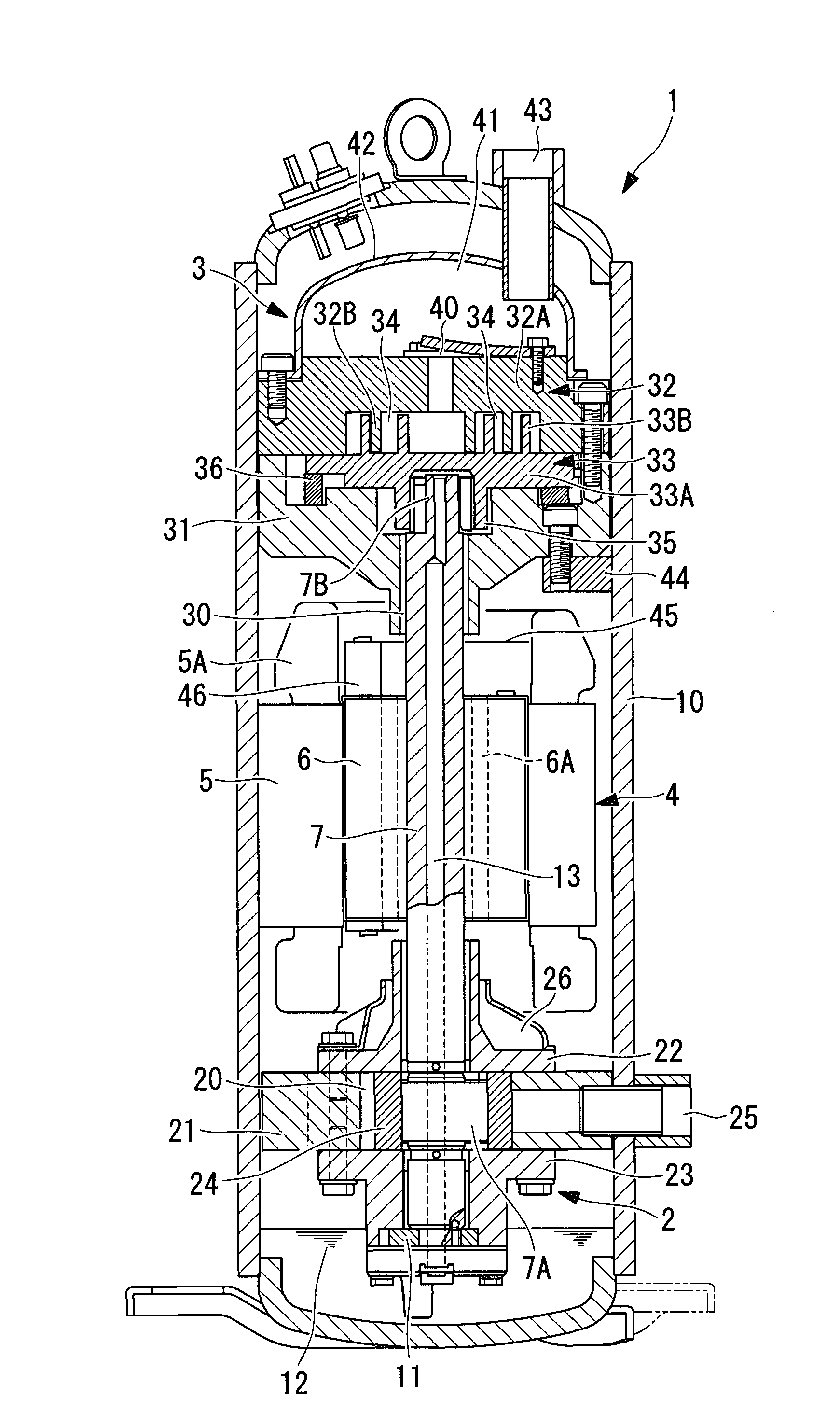
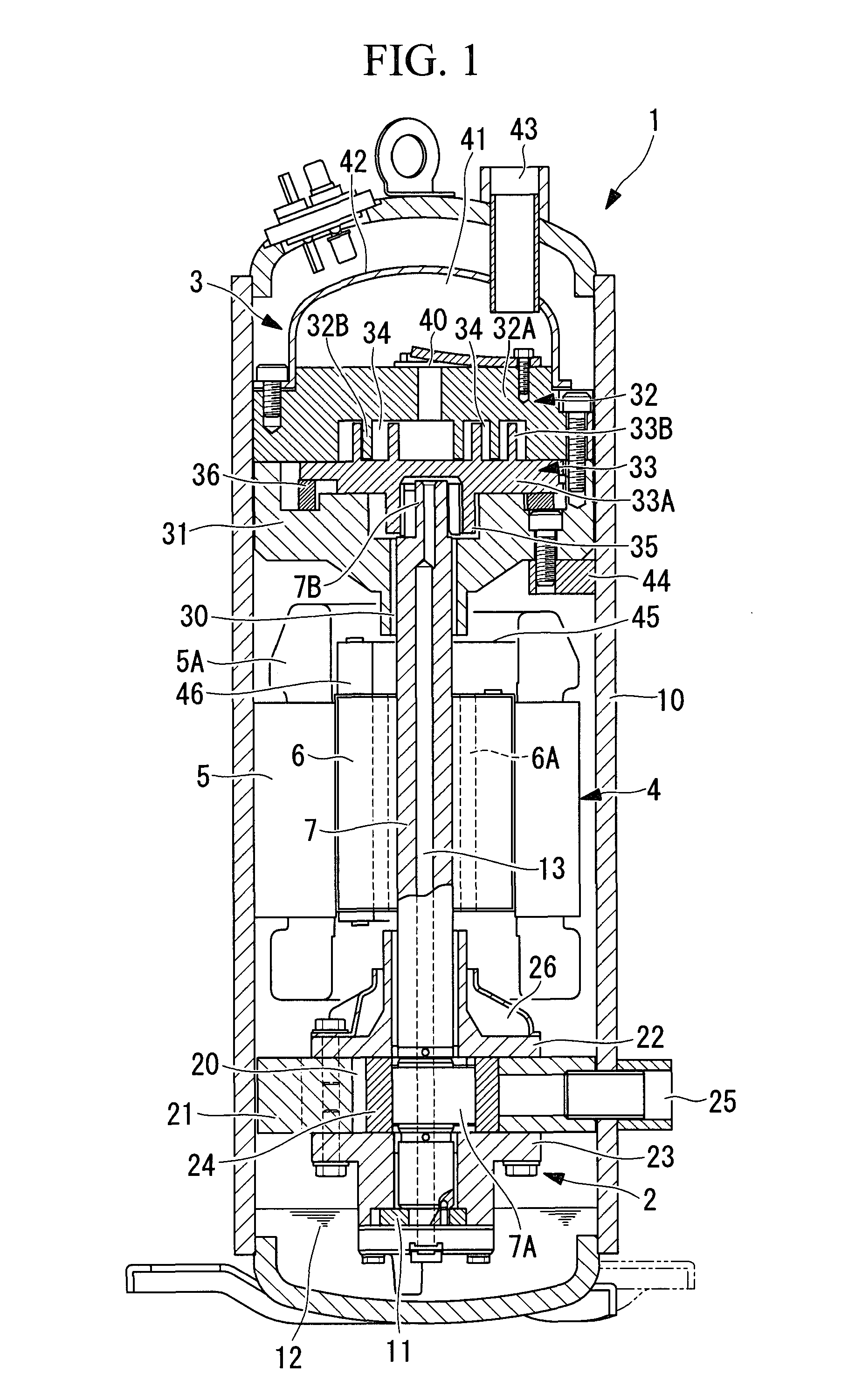
[0076]FIG. 1 is a longitudinal sectional view of a multistage compressor 1 for refrigerating / air-conditioning, which includes a low-stage compression mechanism 2 and a high-stage compression mechanism 3. Although the multistage compressor 1 described as an example in this embodiment employs a rotary compression mechanism as the low-stage compression mechanism 2 and a scroll compression mechanism as the high-stage compression mechanism 3 for the sake of convenience, it is to be noted that the low-stage compression mechanism 2 and the high-stage compression mechanism 3 are not limited to the aforementioned compression mechanisms.

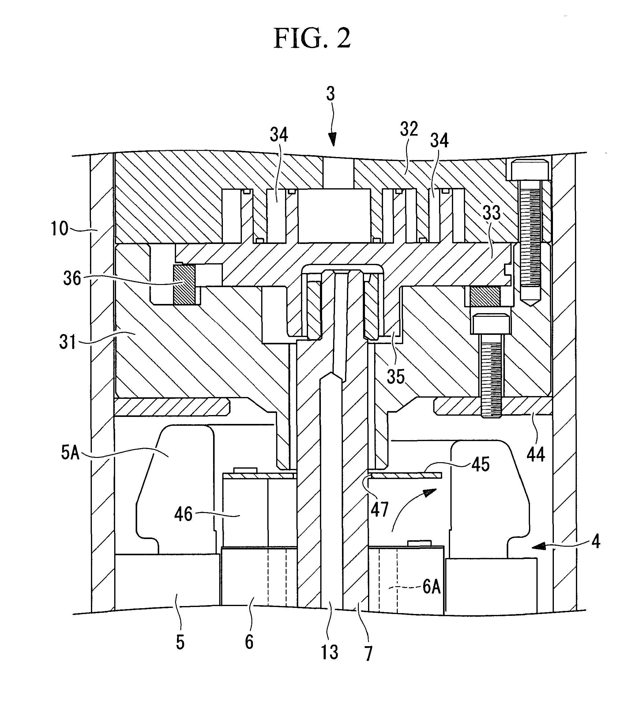
[0077]The multistage compressor 1 includes a sealed housing 10. An electric motor 4 formed of a stator 5 and a rotor 6 is fixed to a substantially central section inside the sealed housing 10. A rotary shaft (crankshaft) 7 is integrally joined to the r...

second embodiment

[0090]A second embodiment of the present invention will now be described with reference to FIG. 3.

[0091]This embodiment differs from the first embodiment in the configuration of an oil separator plate 50. Other points are similar to those in the first embodiment, and therefore, the descriptions thereof will be omitted.

[0092]The oil separator plate 50 in this embodiment has a thickness greater than that of the oil separator plate 45 in the first embodiment. An inner peripheral surface of a through-hole 51, through which the rotary shaft 7 extends, provided at the central section of the oil separator plate 50 is provided with a sealing member 52, such as an O-ring, for sealing the gap between the inner peripheral surface of the through-hole 51 and the outer peripheral surface of the rotary shaft 7.

[0093]As described above, the sealing member 52 seals the gap between the through-hole 51 provided in the oil separator plate 50 and the rotary shaft 7 so as to prevent the intermediate-pres...

third embodiment

[0094]A third embodiment of the present invention will now be described with reference to FIG. 4.

[0095]This embodiment differs from the first embodiment in the configuration of a gas channel 56 that guides the intermediate-pressure refrigerant gas from the space above the electric motor 4 to an intake 55 of the high-stage scroll compression mechanism 3. Other points are similar to those in the first embodiment, and therefore, the descriptions thereof will be omitted.

[0096]In this embodiment, the gas channel 56 that guides the intermediate-pressure refrigerant gas to the intake 55 of the high-stage scroll compression mechanism 3 extends within the supporting member 31, and an inlet 57 thereof is provided on a lower surface 31A of the supporting member 31 at an inner peripheral side relative to the stator coil end 5A of the electric motor 4.

[0097]As described above, because the gas channel 56 that guides the intermediate-pressure refrigerant gas to the intake 55 of the high-stage scro...


PUM


Abstract

A multistage compressor is provided, which can reduce an oil circulation ratio by reducing the amount of lubricating oil to be taken in by a high-stage compression mechanism to improve the system efficiency and prevent a shortage of lubricating oil. A low-stage compression mechanism and a high-stage compression mechanism are disposed below and above to flank an electric motor, respectively, intermediate-pressure refrigerant gas compressed by the low-stage compression mechanism is discharged into a sealed housing, and the intermediate-pressure refrigerant gas is taken in by the high-stage compression mechanism so as to be compressed in two stages, an oil separator plate that centrifugally separates lubricating oil contained in the intermediate-pressure refrigerant gas, which is taken in by the high-stage compression mechanism after passing through the electric motor, is provided at one end of a rotor of the electric motor such that a rotary shaft extends through the oil separator plate.

Description

TECHNICAL FIELD[0001]The present invention relates to a multistage compressor having a low-stage compression mechanism and a high-stage compression mechanism that are provided within a sealed housing and are driven by an electric motor.BACKGROUND ART[0002]Patent Document 1 discusses an example of a multistage compressor having a low-stage compression mechanism and a high-stage compression mechanism that are provided within a sealed housing and are driven by an electric motor. In this multistage compressor, the electric motor is disposed in a substantially central section inside the sealed housing, and a low-stage rotary compression mechanism is disposed below the electric motor, whereas a high-stage scroll compression mechanism is disposed above the electric motor. Moreover, the low-stage rotary compression mechanism and the high-stage scroll compression mechanism are driven by the electric motor via a rotary shaft.[0003]The aforementioned multistage compressor is configured to take...

Claims


Application Information

Patent Timeline
Patent Type & Authority Applications(United States)
IPC IPC(8): F25B43/02F04C23/00F04B39/04
CPCF04C18/0215F04C29/026F04C23/008F04C23/005
Inventor SATO, HAJIMEKIMATA, YOSHIYUKI
Owner MITSUBISHI HEAVY IND LTD
Why Eureka
Try Eureka