Trashcan with hydraulic lid deceleration

a technology of hydraulic deceleration and trash can lid, which is applied in the direction of shock absorbers, refuse gathering, transportation and packaging, etc., can solve the problems of slow lid-opening action, complicated or unsuitable use mechanisms, and noise of lid hitting against the can, etc., to achieve simple structure of the drop-deceleration mechanism of this trash can lid, less force, and easy operation

Inactive Publication Date: 2010-04-08
LU HUANBANG
View PDF0 Cites 55 Cited by
  • Summary
  • Abstract
  • Description
  • Claims
  • Application Information

AI Technical Summary

Benefits of technology

[0006]The tip seats on a fluid aperture on the piston in a closed position. When the gliding rod moves up, the tip is removed from the fluid aperture in an open position allowing hydraulic fluid to flow between the lower chamber and the upper chamber. When the gliding rod glides downward, the tip closes the fluid aperture, and slows hydraulic fluid flow between the lower chamber and the upper chamber.
[0007]To deal with the above mentioned issues, the purpose of this new utility model is to provide one kind of trash can with a hydraulic drop-deceleration mechanism that has a simple structure and is easy to use.
[0009]The advantages of this new utility model are: Because the structure of the drop-deceleration mechanism of this trash can lid is simple, less force is required to open the lid. The opening speed is faster. When the lid is being closed, the closing is slower. No disturbing noise is produced. The operation is easy, dependable, and effective.

Problems solved by technology

During operation, the disturbing noise of the lid hitting against the can is often produced when the lid closes which is an undesirable result.
Although some trash can lids have a drop-deceleration mechanism, such mechanisms are complicated or not ideal for use.
For example, a mechanism that employs a decelerating cable is not dependable; on the other hand, a mechanism that employs a hydraulic decelerator is not only complicated but leads to a comparatively slower lid-opening action which makes its use very inconvenient.

Method used


Image

  • Trashcan with hydraulic lid deceleration
  • Trashcan with hydraulic lid deceleration
  • Trashcan with hydraulic lid deceleration

Examples


Embodiment Construction

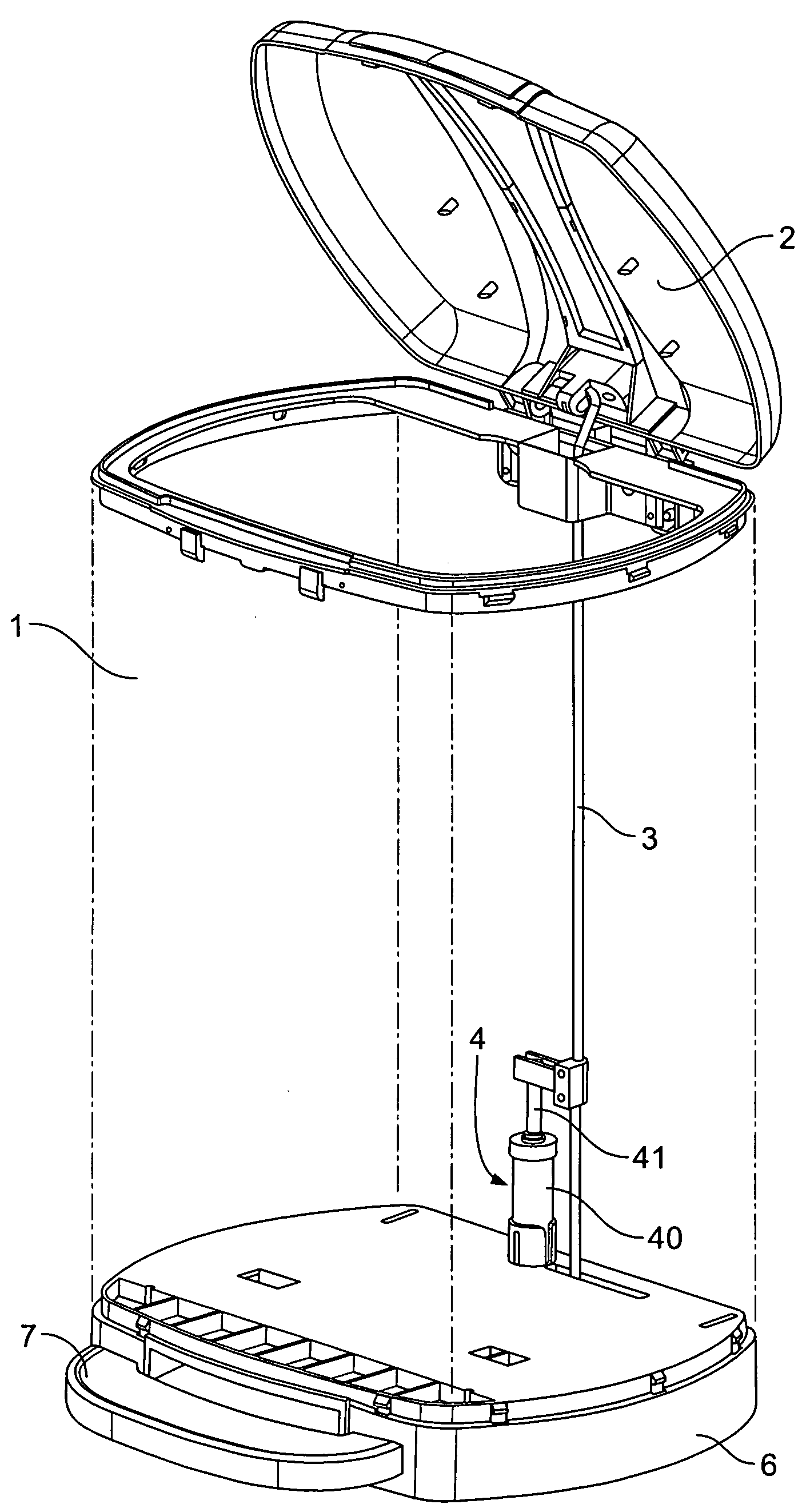
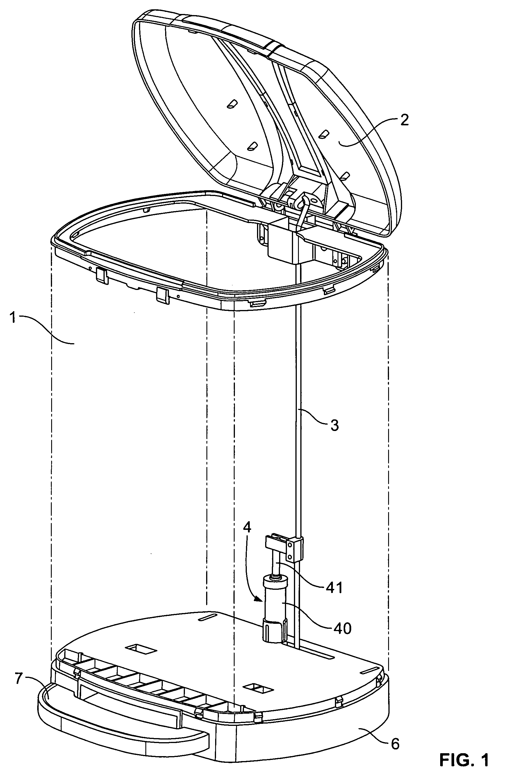
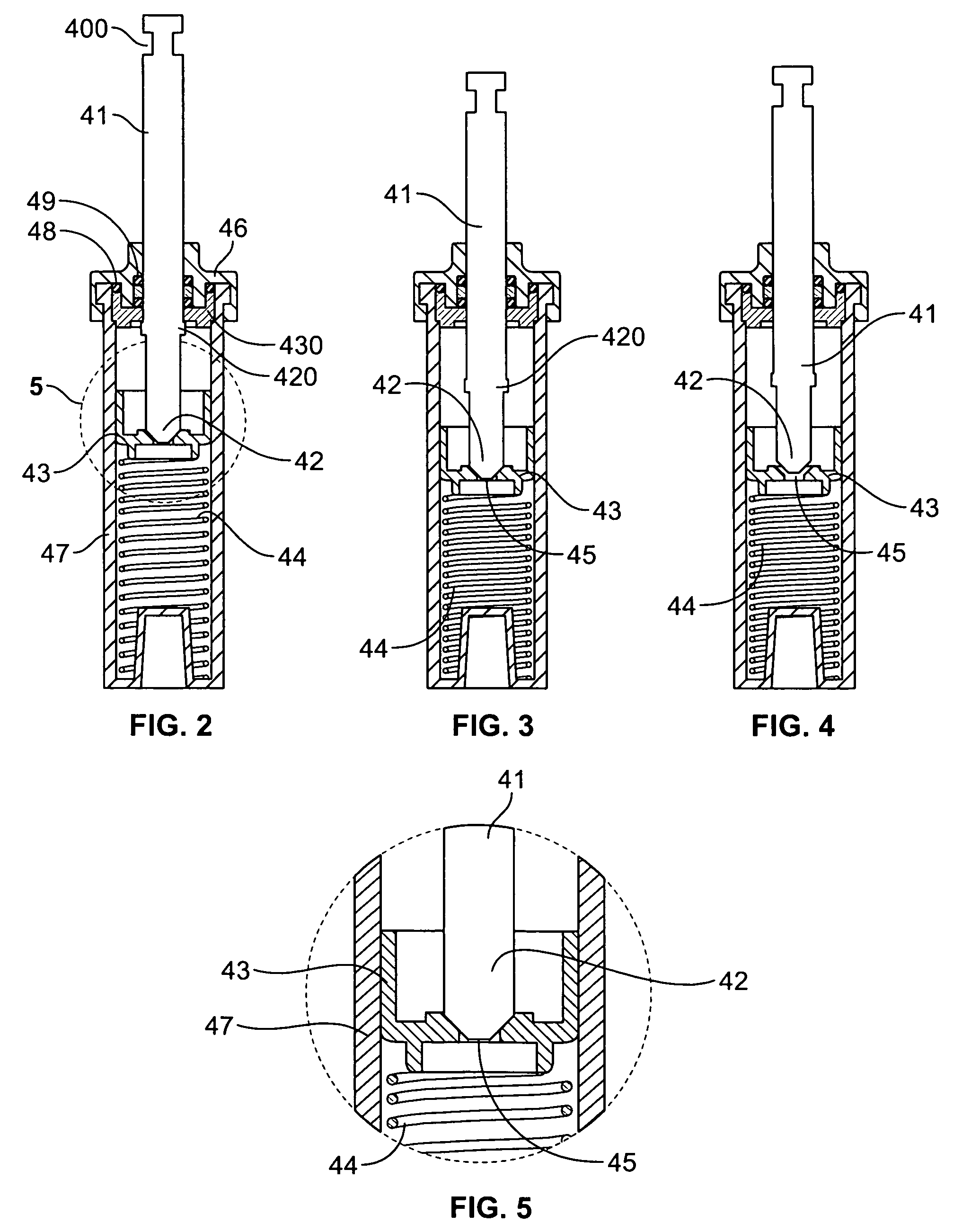
[0056]Referring to FIGS. 1-7, this utility model, which is one kind of trash can with a hydraulic drop-deceleration mechanism, includes: The can 1 and the lid 2 that is installed on top of the can 1. The lid 2 is connected to the push-open connection pole 3 at the top of the push-open mechanism. The push-open mechanism includes a foot pedal 7 that is installed on the base 6 of the trash can. The foot pedal 7 is connected to the push-open connection pole 3. The push-open connection pole 3 could be a metal wire. Said push-open connection pole 3 is connected to the hydraulic drop-deceleration mechanism 4. The hydraulic drop-deceleration mechanism is anchored to the base 6 of the can 1 by the holder 8. The hydraulic drop-deceleration mechanism includes the cylinder 40 and the gliding rod 41. The chamber of the cylinder 40 is filled with hydraulic fluid. The tip 42 of the gliding rod 41 is housed within the chamber of the cylinder 40; the other end [of the gliding rod] is connected to th...


PUM


Abstract

A trashcan has a hydraulic drop-deceleration mechanism including a can body, a lid, and a connection pole for push-open connection. The lid is connected to the connection pole at a top connection pole end. The connection pole is connected to the foot pedal via a lever at a bottom connection pole end. A hydraulic mechanism is for drop-deceleration. The hydraulic mechanism is connected to the connection pole by a connector. The hydraulic mechanism has a chamber filled with hydraulic fluid. The hydraulic mechanism has a gliding rod moving within the chamber. The gliding rod forms a tip at a gliding rod lower end. The mechanism has upper and lower fluid storage chambers. A piston is slidingly mounted in the hydraulic mechanism is biased in a lid open position by a spring.

Description

[0001]This application claims priority from Chinese patent application 200820201712.X filed Oct. 8, 2008, the disclosure of which is incorporated herein by reference.FIELD OF TECHNOLOGY[0002]This utility model involves one kind of trash can, in particular, one kind of trash can with a hydraulic drop-deceleration mechanism.BACKGROUND TECHNOLOGY[0003]A trash can is an indispensable item in our daily lives. To prevent unpleasant odors from spreading around and attracting rats, cockroaches, and flies, most trash cans are covered by a lid on the top open end with the lid hinged to the trash can. The lid is opened by stepping on an opening mechanism, by which: a foot peal is attached to the trash car; the foot pedal is connected to the lid through a push-open connection pole; when the foot pedal is stepped on, the push-open connection pole flips and opens the lid.[0004]Presently, most of the trash can lids with the above-described construction are without a drop-deceleration mechanism. Du...

Claims


Application Information

Patent Timeline
Patent Type & Authority Applications(United States)
IPC IPC(8): F16F9/49
CPCB65F2001/1661B65F1/163
Inventor LU, HUANBANG
Owner LU HUANBANG
Why Eureka
Try Eureka