Mental fatigue detecting method and device
a detection method and mental fatigue technology, applied in the field of mental fatigue detection, can solve the problems of difficult to exclude arbitrariness from mental fatigue evaluation, and achieve the effect of reducing the burden on the test subject and avoiding intentional false measurements or arbitrariness
- Summary
- Abstract
- Description
- Claims
- Application Information
AI Technical Summary
Benefits of technology
Problems solved by technology
Method used
Image
Examples
example 1
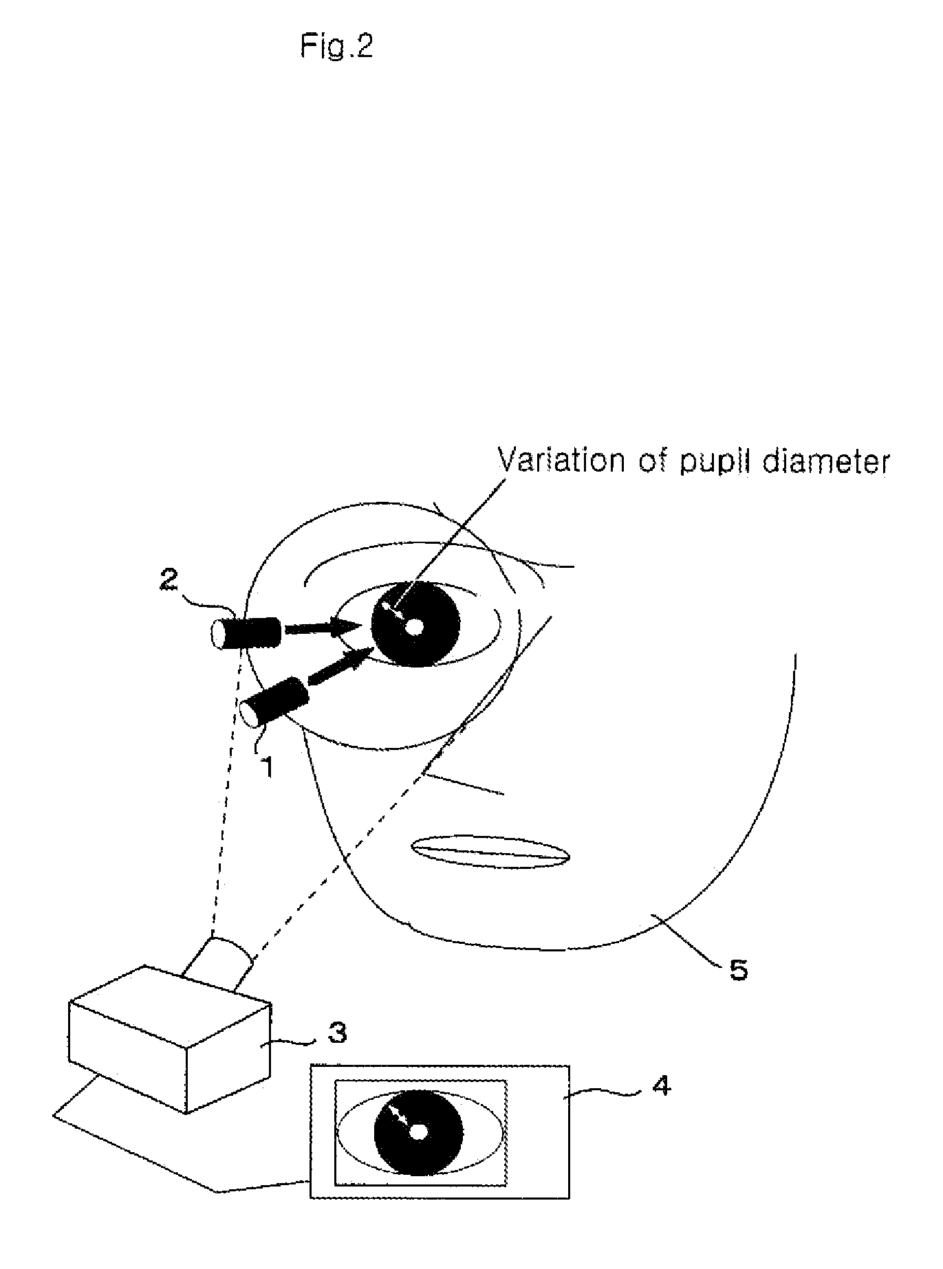
[0162]The first experiment was performed according to the first detection method. Under the flicker stimulation condition of fw=10 (Hz), Δf=1 (Hz), ΔT=2 (seconds), as well as light on (50%) and light off (50%), flicker perception and changes in pupil diameter due to a decrease in the flicker light frequency are observed. Before the experiment, the threshold frequency f0 of the test subject under the above conditions was measured. The result was 34 Hz. Based on this result, the flicker frequency was continuously decreased from the threshold frequency 34 Hz+10 Hz (44 Hz: condition in which the test subject does not perceive the flicker) to the threshold frequency 34 Hz-10 Hz (24 Hz: condition in which the test subject perceives the flicker). The frequency was decreased every two seconds by 1 Hz for about 40 seconds. Images of a pupil of the test subject were taken during this process. Using the obtained data, changes in the number of pixels of the pupil diameter in the vertical direct...
example 2
[0166]An experiment according to the second detection method was performed. Two values, a frequency (a frequency at which the flicker is not perceived) that is 7.5 Hz higher than the flicker perception threshold frequency and a frequency (a frequency at which the flicker is perceived) that is 7.5 Hz lower than the flicker perception threshold frequency, were used as the flicker frequency f. Every 10 seconds of the light (flicker) stimulation ON time (Δton) is followed by 1.5 seconds of the light (flicker) stimulation OFF time (Δtoff). This experiment observes changes in pupil diameter resulting from the on / off operations of the light stimulation before and after the 1.5 second period. As in Example 1, the flicker frequency threshold of the test subject measured before the experiment was 34 Hz, and therefore the flicker frequency at which the flicker is not perceived was set to 41.5 Hz, and the flicker frequency at which the flicker is perceived was set to 26.5 Hz. The imaging of the...
example 3
[0177]The following describes a result of an experiment of a visually evoked magnetoencephalographic reaction. As stated below, it is considered that a similar result can also be obtained from a visually evoked brain potential reaction.
[0178]The flicker of light was presented in the following sequence. First, a flicker signal was turned on and maintained for 1500 ms, and then omission of the light is maintained for 1500 ms; thereafter, another flicker signal at a different frequency was turned on and maintained for 1500 ms. A flickering signal which turns on and off at an interval of 1500 ms was presented to the test subject at varied flicker frequencies, thereby finding the flicker frequency threshold of the test subject. Based on the obtained frequency threshold, the frequencies of the flickering signal to be presented were determined. More specifically, the light flicker frequencies were determined to be two high frequencies 2.5 Hz and 7.5 Hz higher than the threshold frequency a...
PUM
 Abstract
Description
Claims
Application Information
 - R&D
- Intellectual Property
- Life Sciences
- Materials
- Tech Scout
- Unparalleled Data Quality
- Higher Quality Content
- 60% Fewer Hallucinations
Browse by: Latest US Patents, China's latest patents, Technical Efficacy Thesaurus, Application Domain, Technology Topic, Popular Technical Reports.
© 2025 PatSnap. All rights reserved.Legal|Privacy policy|Modern Slavery Act Transparency Statement|Sitemap|About US| Contact US: help@patsnap.com


