Circuit arrangement comprising at least two capacitors connected in series

a circuit arrangement and capacitor technology, applied in the direction of emergency protective circuit arrangement, safety/protection circuit, battery arrangement for several simultaneous batteries, etc., can solve the problems of capacitor short circuit, increased component cost, and failure of desired voltage limit of individual capacitors

Inactive Publication Date: 2010-04-08
SIEMENS AG
View PDF6 Cites 9 Cited by
  • Summary
  • Abstract
  • Description
  • Claims
  • Application Information

AI Technical Summary

Benefits of technology

[0020]Configuration as an optical coupler is advantageous for the coupling elements. Optical couplers are proven structural elements, which ensure electrical isolation between a transmit part configured as a light-emitting diode and a receiver part configured as a phototransistor.

Problems solved by technology

Such series circuits comprising a number of capacitors have the disadvantage that the desired voltage limiting for the individual capacitors fails when a fault occurs, during which a capacitor short circuits.
This has the disadvantage of increasing component costs and the need to provide an additional circuit indicating the failure of a capacitor.

Method used


Image

  • Circuit arrangement comprising at least two capacitors connected in series
  • Circuit arrangement comprising at least two capacitors connected in series
  • Circuit arrangement comprising at least two capacitors connected in series

Examples


Embodiment Construction

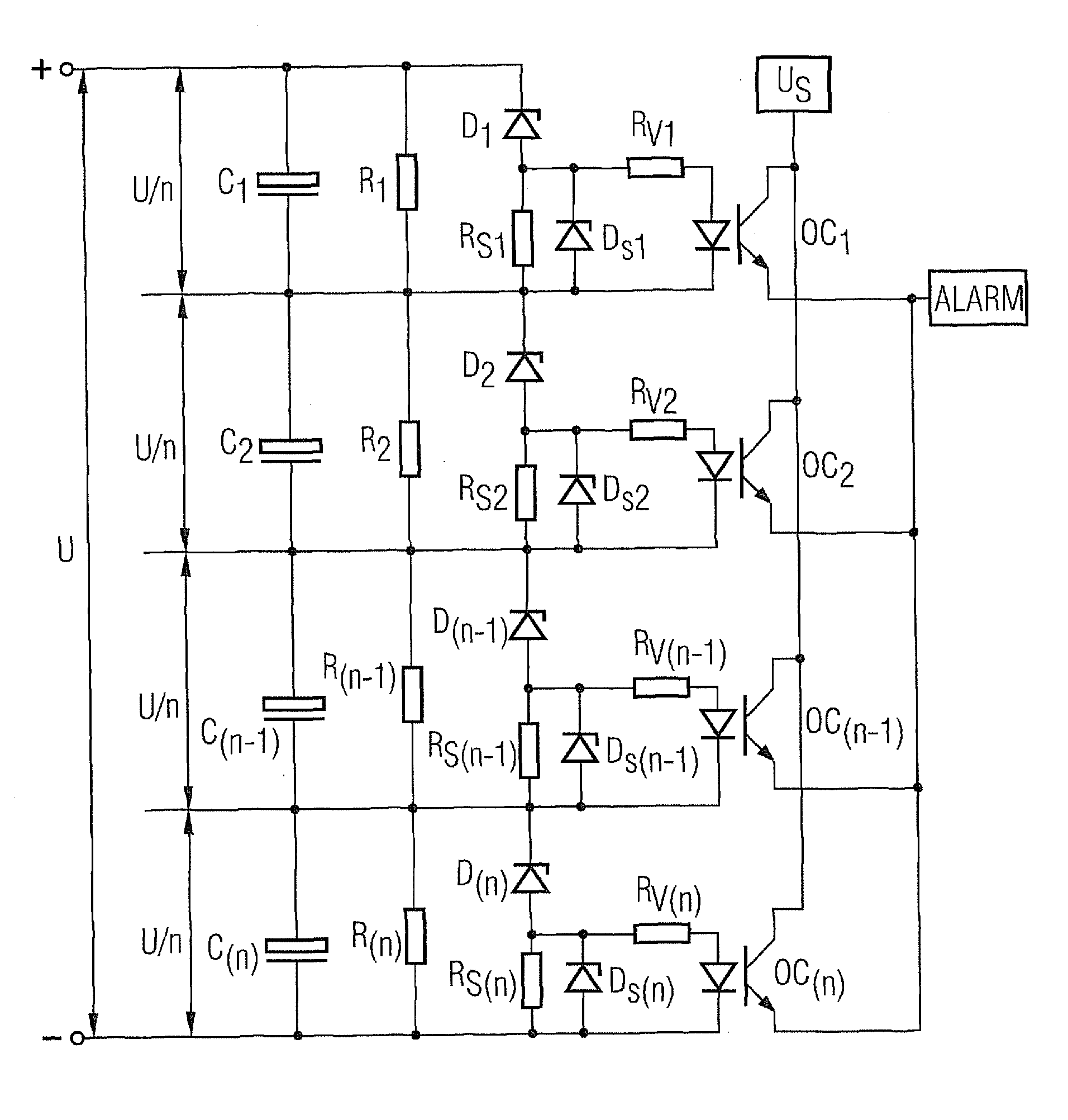
[0027]FIG. 1 shows the embodiment of an inventive circuit arrangement with a number of capacitors C1 . . . C(n) arranged in series, with an index i=1 to n being assigned to each capacitor Ci to simplify the description which follows. The number n of capacitors C1 . . . C(n) is a function here of the voltage U present, the rated voltages of the capacitors C1 . . . C(n) and the voltage division between the individual capacitors C1 . . . C(n).

[0028]The voltage division is predetermined by a voltage divider. In the simplest instance the voltage divider is formed, as shown in FIG. 1, from a number of resistances R1 . . . R(n), a resistance Ri being connected parallel to each capacitor Ci. The voltage U is divided according to the resistance values between the individual capacitors Ci. Where the resistance values are the same, the same partial voltage U / n is present at each capacitor Ci.

[0029]A series circuit consisting of a protective diode Di and a series resistance RSi is connected par...


PUM


Abstract

A circuit arrangement including at least two capacitors that are connected in series to a voltage is provided. The circuit arrangement also includes a voltage divider, arranged in parallel to the at least two capacitors, the voltage divider divides the voltage to the at least two capacitors, and a protective diode arranged in parallel to every capacitor in series to a series resistance in such a manner that the threshold voltage of the protective diode is lower than the admissible voltage of the capacitor arranged in parallel to the protective diode. In addition a protective circuit is arranged in parallel to the series resistances.

Description

CROSS REFERENCE TO RELATED APPLICATIONS[0001]This application is the US National Stage of International Application No. PCT / EP2008 / 054537, filed Apr. 15, 2008 and claims the benefit thereof The International Application claims the benefits of Austrian application No. A717 / 2007 AT filed May 10, 2007, both of the applications are incorporated by reference herein in their entirety.FIELD OF INVENTION[0002]The invention relates to a circuit arrangement comprising at least two capacitors connected in series to a voltage, a voltage divider being arranged parallel to the at least two capacitors, which divides the voltage between the at least two capacitors.BACKGROUND OF INVENTION[0003]According to the prior art capacitors are connected in series if the voltage to be applied is greater than the permissible voltage of an individual capacitor. Electrolytic capacitors (ELKO) are available in sizes up to approx. 500 V rated voltage for example. Therefore for applications which provide for the st...

Claims


Application Information

Patent Timeline
Patent Type & Authority Applications(United States)
IPC IPC(8): H02H7/16
CPCH02H7/16H02J7/345H02J7/0026H02J7/0014H02J7/00308
Inventor HALLAK, JALALKERNSTOCK, HARALD
Owner SIEMENS AG
Why Eureka
Try Eureka