Switching power supply apparatus

a power supply apparatus and switching technology, applied in the direction of power conversion systems, dc-dc conversion, instruments, etc., can solve the problems of reducing output voltage vo by vo, affecting the efficiency of inability to supply a sufficient current id of the switching device to the switching power supply apparatus, so as to reduce consumption current

Active Publication Date: 2010-04-08
PANNOVA SEMIC
View PDF13 Cites 16 Cited by
  • Summary
  • Abstract
  • Description
  • Claims
  • Application Information

AI Technical Summary

Benefits of technology

[0036]With this, it is possible to reduce the consumption current of the control circuit during the light-load period.
[0037]In addition, the oscillator may generate a second clock signal for limiting a maximum length of period for which the drive pulse signal remains active.

Problems solved by technology

However, in a conventional switching power supply apparatus, there is a problem of transitional change in output voltage which is caused by a delay in response of the control terminal voltage in the case of sudden change in the load current.
That is, during the period from t51 to t52, it is not possible to supply a sufficient switching device current ID to the switching power supply apparatus.
This causes a problem in the conventional switching power supply apparatus that the output voltage VO decreases by ΔVO as shown at time t52.

Method used


Image

  • Switching power supply apparatus
  • Switching power supply apparatus
  • Switching power supply apparatus

Examples


first embodiment

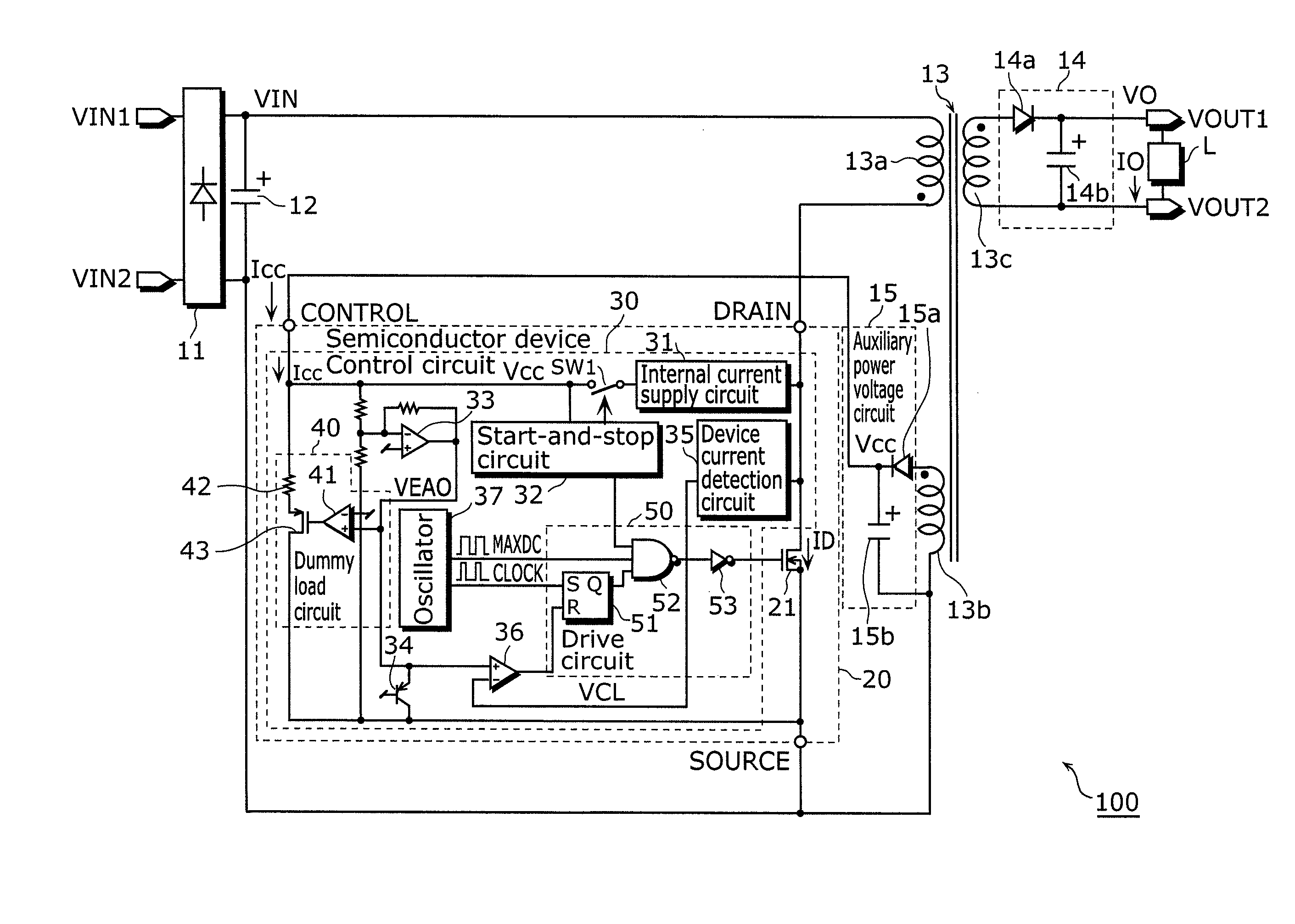
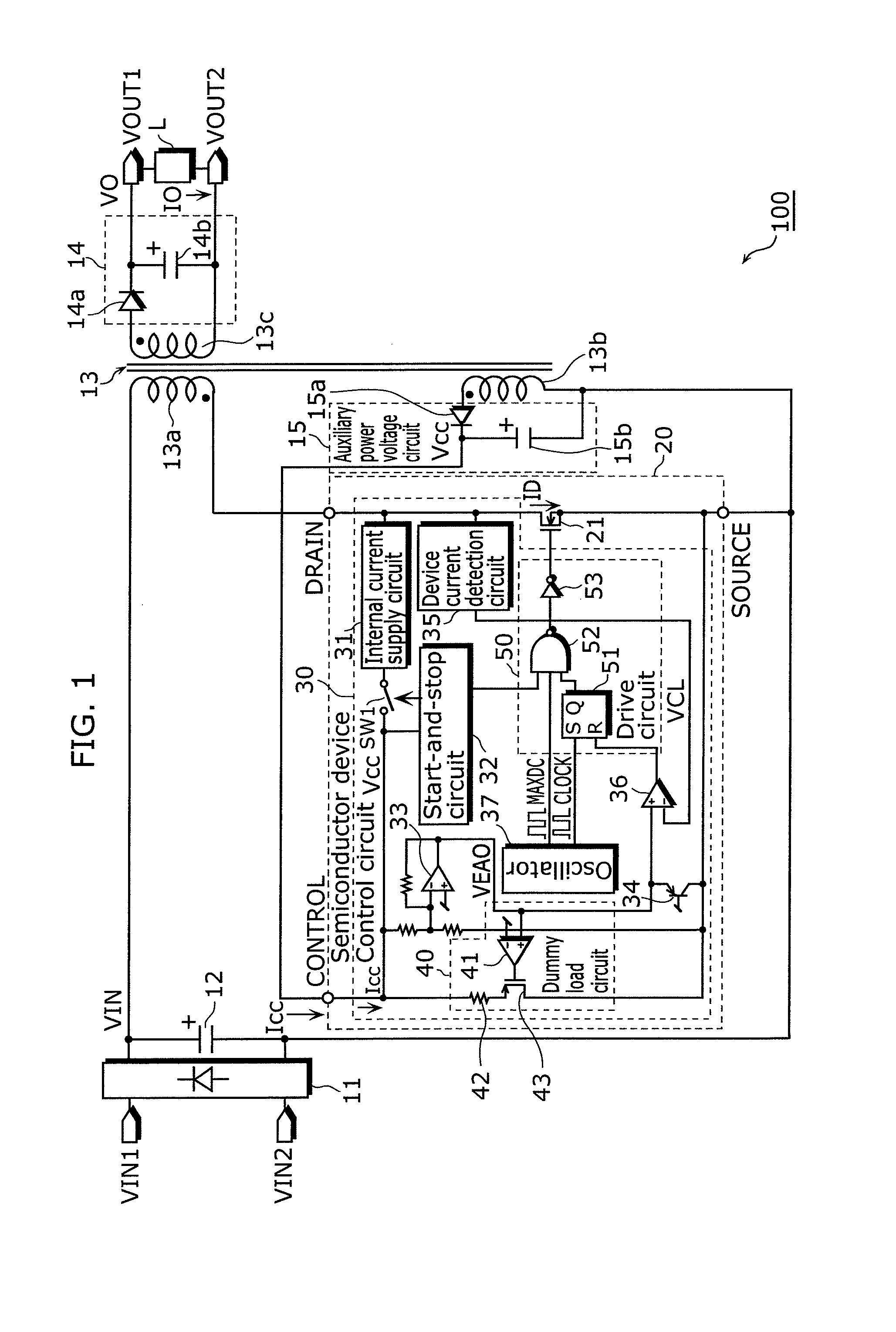
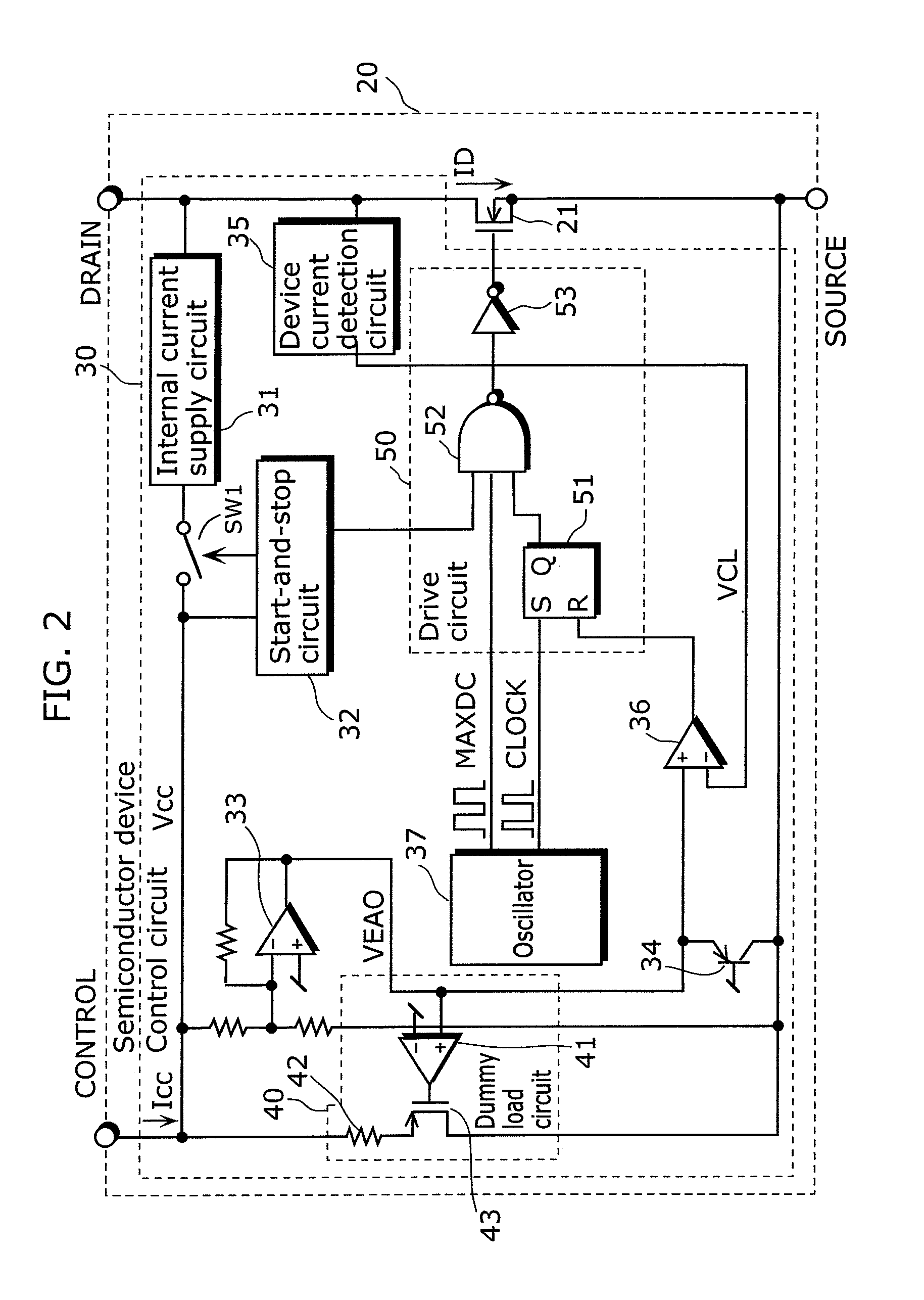
[0058]A switching power supply apparatus according to the first embodiment of the present invention includes: a transformer including a primary winding, a secondary winding, and an auxiliary winding; a switching device connected in series with the primary winding; an auxiliary power voltage circuit which is connected to the auxiliary winding and generates an auxiliary power voltage by using an alternating-current voltage induced in the auxiliary winding; and a control circuit which controls an operation of the switching device, and the control circuit includes: a power source terminal through which the auxiliary power voltage is supplied; a difference device which generates a difference voltage depending on a difference between the auxiliary power voltage and a first reference voltage; a device current detection circuit which detects a device current flowing in the switching device, and generates a device current detection signal indicating an amount of the device current; a drive c...

second embodiment

[0102]Next is a description of a switching power supply apparatus according to a second embodiment of the present invention. The switching power supply apparatus according to the present embodiment is almost the same as the switching power supply apparatus 100 according to the first embodiment, but is different in the structure of the dummy load circuit. The description below will center on differences from the first embodiment.

[0103]FIG. 4 is a circuit diagram showing an example of a configuration of the switching power supply apparatus according to the second embodiment of the present invention, and FIG. 5 is a circuit diagram showing an example of a configuration of a semiconductor device in the switching power supply apparatus according to the second embodiment of the present invention. Note that in FIGS. 4 and 5, the same numerical references are given to the same constituent elements as those in the switching power supply apparatus 100 of the first embodiment of the present in...

third embodiment

[0121]Next is a description of a switching power supply apparatus according to a third embodiment of the present invention. The switching power supply apparatus according to the present embodiment is almost the same as the switching power supply apparatus 100 according to the first embodiment, but is different in that the control circuit further includes an intermittent oscillation circuit and in the structure of the dummy load circuit.

[0122]FIG. 7 is a circuit diagram showing an example of a configuration of the switching power supply apparatus according to the third embodiment of the present invention, and FIG. 8 is a circuit diagram showing an example of a structure of a semiconductor device included in the switching power supply apparatus according to the third embodiment of the present invention. Note that in FIGS. 7 and 8, the same numerical references are given to the same constituent elements as those in the switching power supply apparatus 100 of the first embodiment of the...


PUM


Abstract

A switching power supply apparatus according to the present invention includes a switching device and a control circuit, and the control circuit includes: a control terminal through which an auxiliary power voltage is supplied; an error amplifier which generates a difference voltage depending on a difference between a control terminal voltage and a first reference voltage; a device current detection circuit which generates a device current detection signal indicating an amount of a current flowing in the switching device; a drive circuit which generates a drive pulse signal having a duty cycle based on a difference between the difference voltage and the device current detection signal and drives the switching device by using the generated drive pulse signal; and a dummy load circuit through which a dummy load current flows from the control terminal when the difference voltage becomes equal to or higher than a second reference voltage.

Description

BACKGROUND OF THE INVENTION[0001](1) Field of the Invention[0002]The present invention relates to a switching power supply apparatus, and particularly relates to a switching power supply apparatus which inhibits change in output voltage when there is a sudden change in load.[0003](2) Description of the Related Art[0004]A conventional switching power supply apparatus is described with reference to the drawings.[0005]FIG. 13 is a circuit diagram showing a circuit configuration of a switching power supply apparatus of which an input side and an output side are electrically insulated. The switching power supply apparatus shown in the figure includes, for example, a switching device 104 made up of a power MOSFET and so on and a control circuit 130 which controls the switching device 104.[0006]In the switching power supply apparatus shown in FIG. 13, for example, an alternating current (AC) which is inputted to a main input terminal from a commercial power source is rectified by a rectifi...

Claims


Application Information

Patent Timeline
Patent Type & Authority Applications(United States)
IPC IPC(8): H02M3/26
CPCH02M3/33507
Inventor MIMURA, KOHEI
Owner PANNOVA SEMIC
Why Eureka
Try Eureka