Voltage Drive System With Hysteretic Current Control And Method Of Operating The Same

Active Publication Date: 2010-04-08
DRS NAVAL POWER SYST INC
View PDF11 Cites 35 Cited by
  • Summary
  • Abstract
  • Description
  • Claims
  • Application Information

AI Technical Summary

Benefits of technology

[0020]Systems and articles of manufacture consistent with the present invention provide a voltage drive system having a single-phase output signal to drive a load, such as a variable speed motor. The voltage drive system comprises a plurality of modulators and a plurality of switching circuits. A first of the modulators includes a first signal generator and a first adder. The first modulator receives a phase current error that reflects on a difference between a current reference and a current value of the single-phase output signal, and generates a first gate input based on the phase current error. The first switching circuit receives the first gate input and generates a first output terminal voltage based on the first gate input. The first signal generator generates a first reference signal having a first phase. The first adder receives the phase current error and the first reference signal and generates a first modulated phase current error based on the regulated phase current error and the first reference signal. The first modulator changes the first gate input from a first voltage level to a second voltage level to effectively cause a first switching event of the first switching circuit when the first modulated phase current error changes from being within a predetermined current range to being outside of the predetermined current range. A second of the modulators includes a second signal generator and

Problems solved by technology

These conventional voltage drive systems usually operate at medium voltages of 1.5 kV to 13.2 kV, as operation at low voltages leads to excessive currents and losses.
While these drives can be manufactured using high voltage devices, the selection and availability of such devices is limited and they are severely lacking in switching speed.
This limitation is significant, as the switching frequency determines the bandwidth of the voltage drive system, which in turn dictates the output waveform quality.
However, the conventional deterministic controller 120 causes significant distortion of the output waveforms when the fundamental frequency of the output waveform to be synthesized and the corr

Method used


Image

  • Voltage Drive System With Hysteretic Current Control And Method Of Operating The Same
  • Voltage Drive System With Hysteretic Current Control And Method Of Operating The Same
  • Voltage Drive System With Hysteretic Current Control And Method Of Operating The Same

Examples


Embodiment Construction

[0038]Reference will now be made in detail to implementations in accordance with methods, systems, and products consistent with the present invention as illustrated in the accompanying drawings.

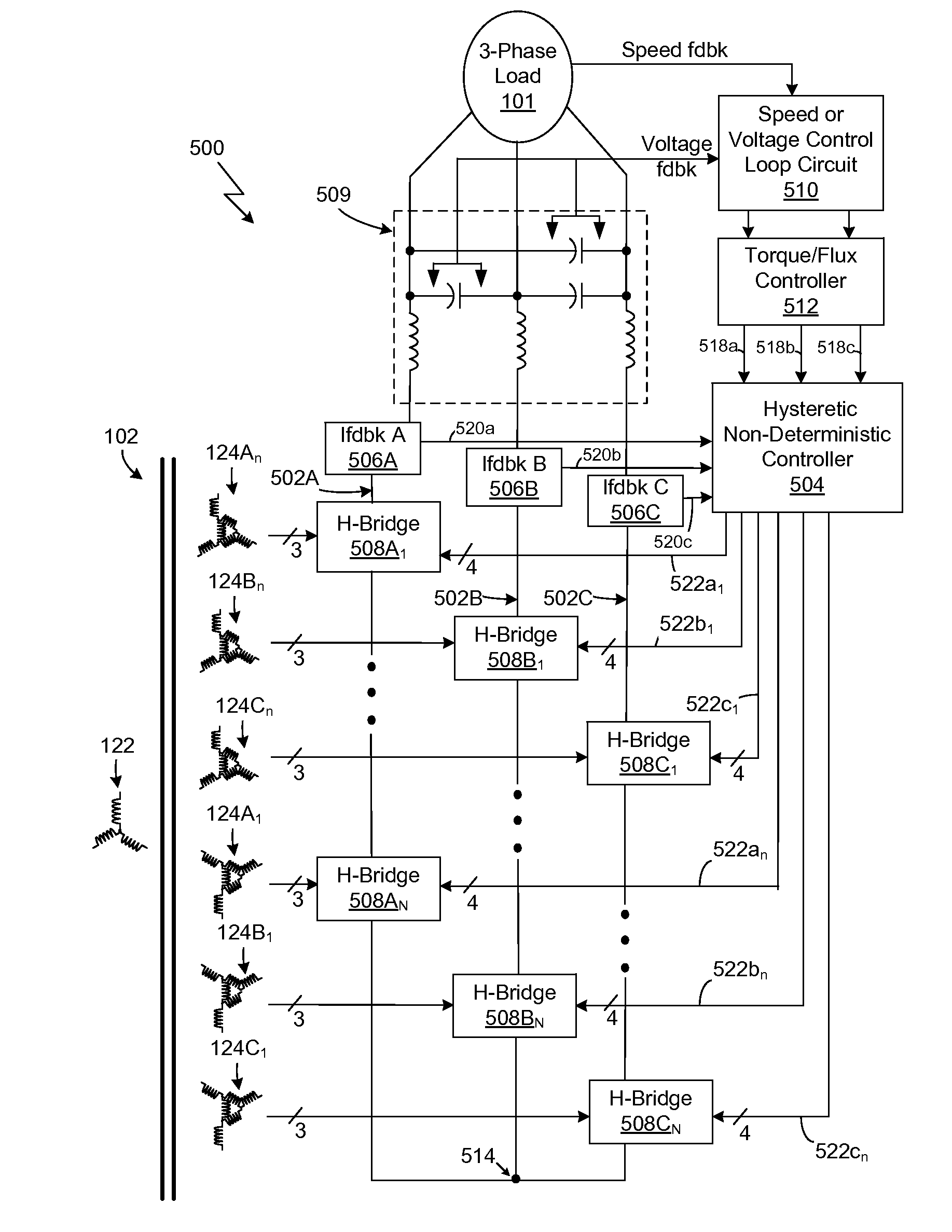
[0039]FIG. 5 illustrates a block diagram of an exemplary voltage drive system 500 consistent with the present invention. In the implementation shown in FIG. 5, the voltage drive system 500 is depicted as driving a three-phase load 101. For example, the three-phase load 101 may be a medium voltage pulse modulated, induction, or synchronous motor requiring three phase, alternate current at variable frequency to control the speed of the motor. However, as described in detail herein, voltage drive systems 500 and 900 consistent with the present invention may be configured to generate one or more single-phase output signals to control or drive a motor or other load.

[0040]The voltage drive system 500 includes phase output lines 502A, 502B, and 502C (which respectively represent Phase A, Phase B, an...


PUM


Abstract

A voltage drive system is provided having a plurality of modulators and a plurality of cascaded switching circuits which collectively generate a single-phase output signal to a load. Each modulator receives a phase current error and has an adder which generates a modulated phase current error based on the phase current error and based on a signal having a phase. For each respective modulator, the phase of the respective signal is different. Each respective modulator changes a respective gate input when the respective modulated phase current error changes from being within a predetermined current range to being outside of the predetermined current range. Each respective switching circuit receives the respective gate input and generates a respective output terminal voltage based on the respective gate input. The change in the respective gate input effectively causes a switching event of the respective switching circuit.

Description

FIELD OF INVENTION[0001]*The present invention generally relates to a voltage drive system. More particularly, the present invention relates to a voltage drive system employing an improved hysteretic current control technique.[0002]Typically, variable frequency voltage drive systems are used to control variable speed, medium voltage motors to drive systems requiring 5 MW to 75 MW of power. These conventional voltage drive systems usually operate at medium voltages of 1.5 kV to 13.2 kV, as operation at low voltages leads to excessive currents and losses. While these drives can be manufactured using high voltage devices, the selection and availability of such devices is limited and they are severely lacking in switching speed. This limitation is significant, as the switching frequency determines the bandwidth of the voltage drive system, which in turn dictates the output waveform quality.[0003]Certain conventional medium voltage drive systems (such as depicted in FIGS. 1-3) employ low...

Claims


Application Information

Patent Timeline
IPC IPC(8): H02M7/5387
CPCH02M7/53875H02M7/483
Inventor ULRICH, JAMES A.BENDRE, ASHISH R.
Owner DRS NAVAL POWER SYST INC
Why Eureka
Try Eureka