
Hot-formed profile

a metal profile and hot-formed technology, applied in the direction of superstructure subunits, building components, structural elements, etc., can solve the problems of limited precision, limited extent, and only possible further forming process, and achieve high overall stability of metal profiles, reduce strength, and high strength of metal profiles

Inactive Publication Date: 2010-04-08
THYSSENKRUPP STEEL EURO AG
View PDF22 Cites 26 Cited by
  • Summary
  • Abstract
  • Description
  • Claims
  • Application Information

AI Technical Summary

Benefits of technology

[0005]In general, an aspect of the present invention is to provide a method for producing the metal profile which enables a metal profile with high strength to be produced at low cost. In addition another aspect of the present invention is to make available metal profiles which can be produced economically. Furthermore an advantageous use of the metal profiles shall be proposed.
[0006]In accordance with a first teaching of the present invention the aspect described above is achieved in that the metal component, before forming, is heated at least partially along at least one bending edge in such a way that the strength is reduced in the heated region after heating.
[0007]It has turned out that by locally heating a bending edge of a hot-formed and press-hardened metal component, preferably to temperatures above a phase change temperature, for example the austenite formation temperature, the strength at the bending edge can be reduced in such a way that the metal component can be formed at the bending edge to a greater extent and with substantially less effort. Due to the bending edge being heated to temperatures above the phase change temperature, the predominantly martensitic structure of a hot-formed and press-hardened metal component transforms into an austenitic microstructure. Thus, after cooling, the region can exhibit a non-martensitic structure with reduced strength for example. These regions can then be used as bending edges.

Problems solved by technology

It is a disadvantage however when using such components that, due to the high strength, a further forming process is only possible at very high effort and also only to a limited extent and with limited precision.

Method used


Image

  • Hot-formed profile
  • Hot-formed profile
  • Hot-formed profile

Examples


Embodiment Construction

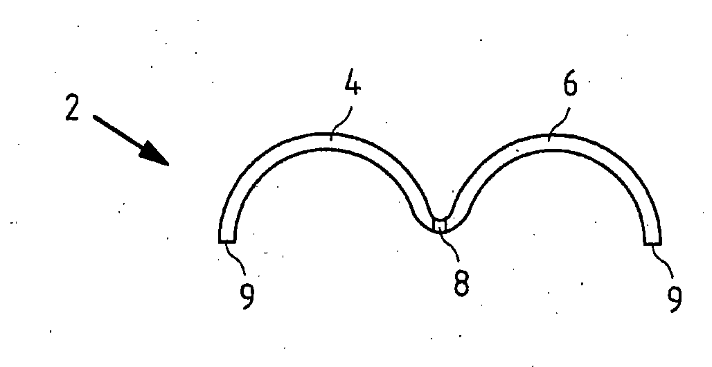
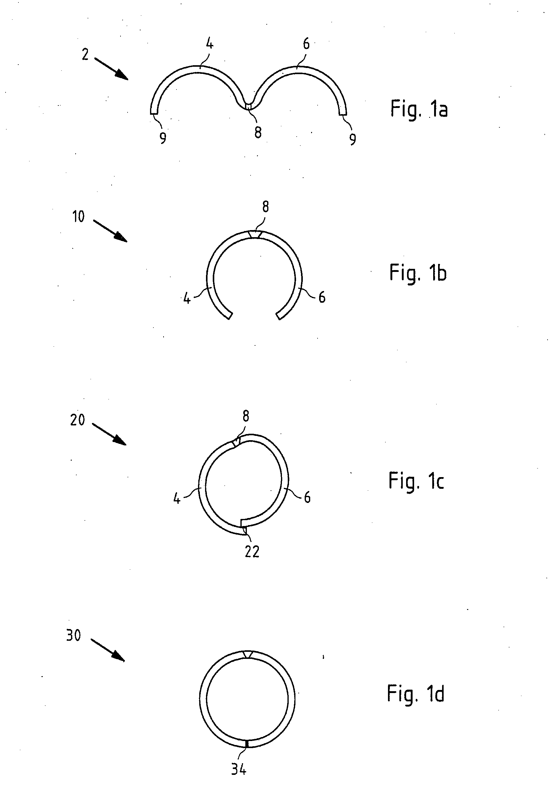
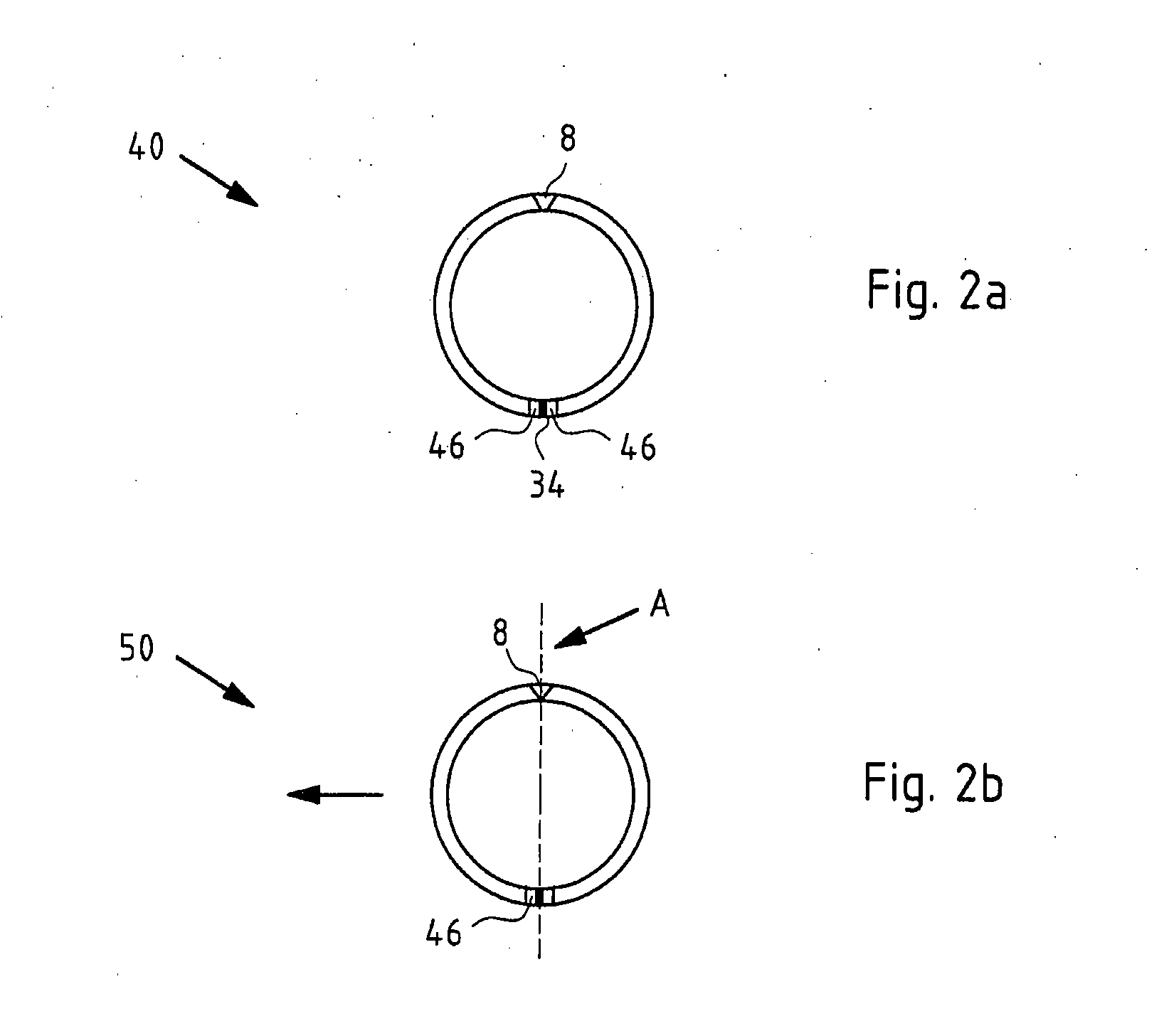
[0035]FIG. 1a shows in cross section a metal component 2, hot formed and press hardened from a blank, during the production of an inventive metal profile in accordance with a first exemplary embodiment of the inventive method. The blank for example can consist of a high or maximum strength steel, preferably a manganese boron steel alloy, e.g. of the 22MnB5 type. The metal component 2 exhibits a left outside region 4 and a right outside region 6, as well as a bending edge 8 arranged in-between. The left outside region 4 and the right outside region 6 were transformed, oriented on use, in the preceding hot forming and press hardening process, so that the metal component 2 exhibits a W-shaped cross section. The side edges 9 of the metal component 2, after forming, point in the same direction. In the production process of the metal profile the bending edge 8 has already been heated by means of a laser beam, so that the metal component 2 exhibits lower strength at the bending edge 8 than...


PUM

PropertyMeasurementUnit
temperaturesaaaaaaaaaa
widthaaaaaaaaaa

Abstract

A method for producing a metal profile includes producing a metal component from a semi-finished product or a blank by a hot forming and hardening process and bending the metal component along at least one bending edge. Bending is simplified according to the invention in that, before forming, the metal component is heated along the bending edge in such a way that the strength is reduced in a heated region after heating. The metal profile, produced with this method, has at least one bending edge at which the strength of the metal profile is reduced. In addition the metal profile can be used in a motor vehicle body, in particular as A- and / or B-pillar.

Description

CROSS-REFERENCE TO RELATED APPLICATIONS[0001]This application claims the benefit of and priority to German Patent Application No. DE 10 2008 044 523.1, filed Sep. 15, 2008, the disclosures of which is incorporated herein by reference in its entirety.FIELD OF THE INVENTION[0002]The invention relates to a method for producing a metal profile, in which a metal component is produced from a semi-finished product or a blank by a hot forming and press hardening process and the metal component is bent along at least one bending edge. The invention also relates to a metal profile with at least one bending edge, produced according to this method, as well as the use of the metal profile in a motor vehicle body.BACKGROUND[0003]In many fields of application, particularly however in the automotive industry, high-strength metal components are used in order to obtain products which are as thin as possible and therefore as light-weight as possible with the same strength properties. For example side ...

Claims


Application Information

Patent Timeline
Patent Type & Authority Applications(United States)
IPC IPC(8): B21D37/16B21D7/16B21D53/88
CPCB21C37/08B21D47/01B21D53/88B23K26/26B62D25/04Y10T29/49622C21D7/13C21D2211/008C21D2221/00Y10T428/12354Y10T428/1241C21D1/673B23K2101/006
Inventor PATBERG, LOTHAR
Owner THYSSENKRUPP STEEL EURO AG
Learn More