

Process For Creating Shape-Designed Particles In A Fluid
a technology of fluid and shape design, applied in the field of process and system for making particles, can solve the problems of reducing the surface area and production rate, difficult to achieve good mechanical contact between the two plates over large surface areas, and affecting the reproducibility of mechanical imprinting in the production setting
- Summary
- Abstract
- Description
- Claims
- Application Information
AI Technical Summary
Problems solved by technology
Method used
Image

Examples
first example embodiment
the RRT Process
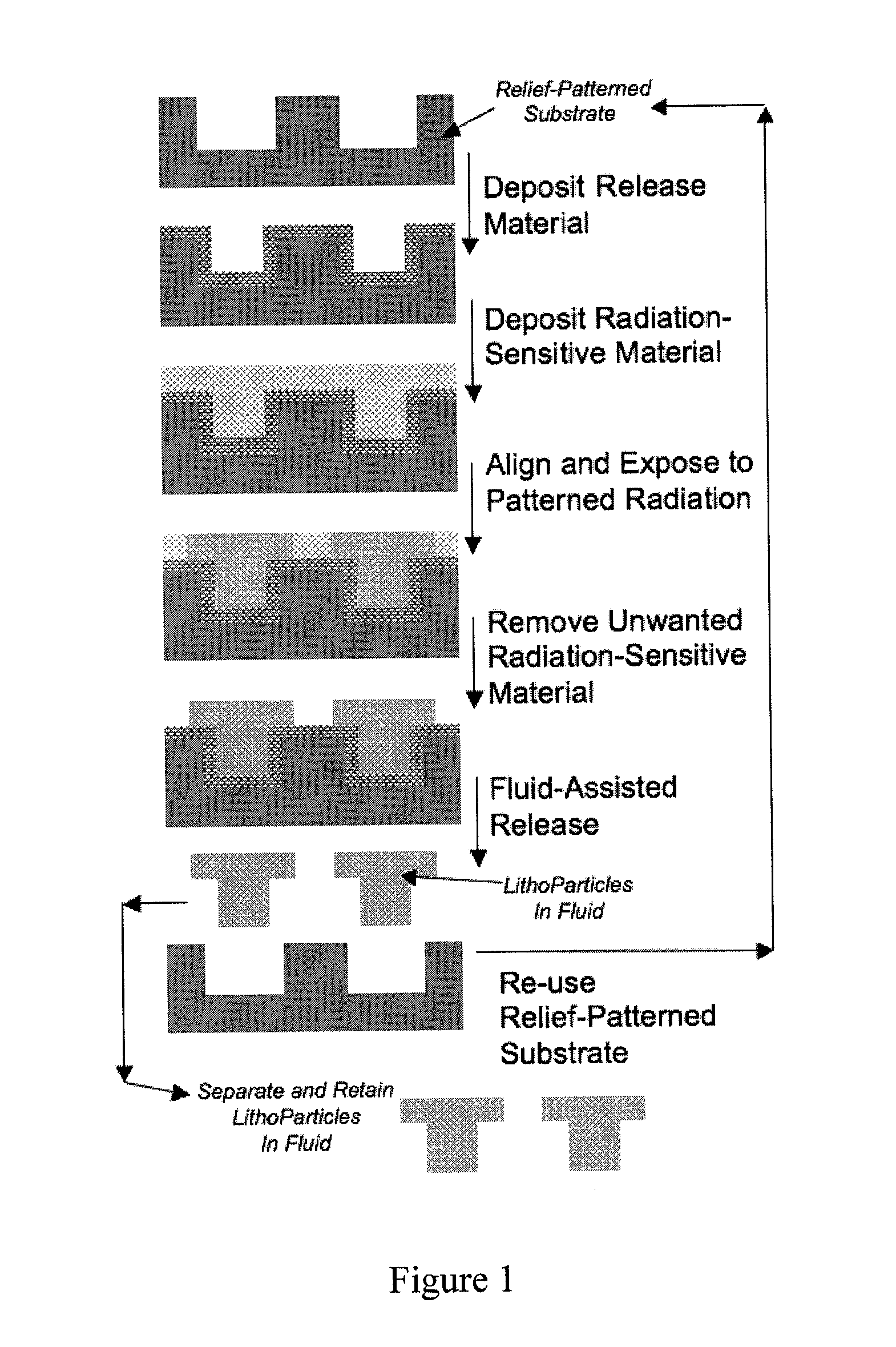
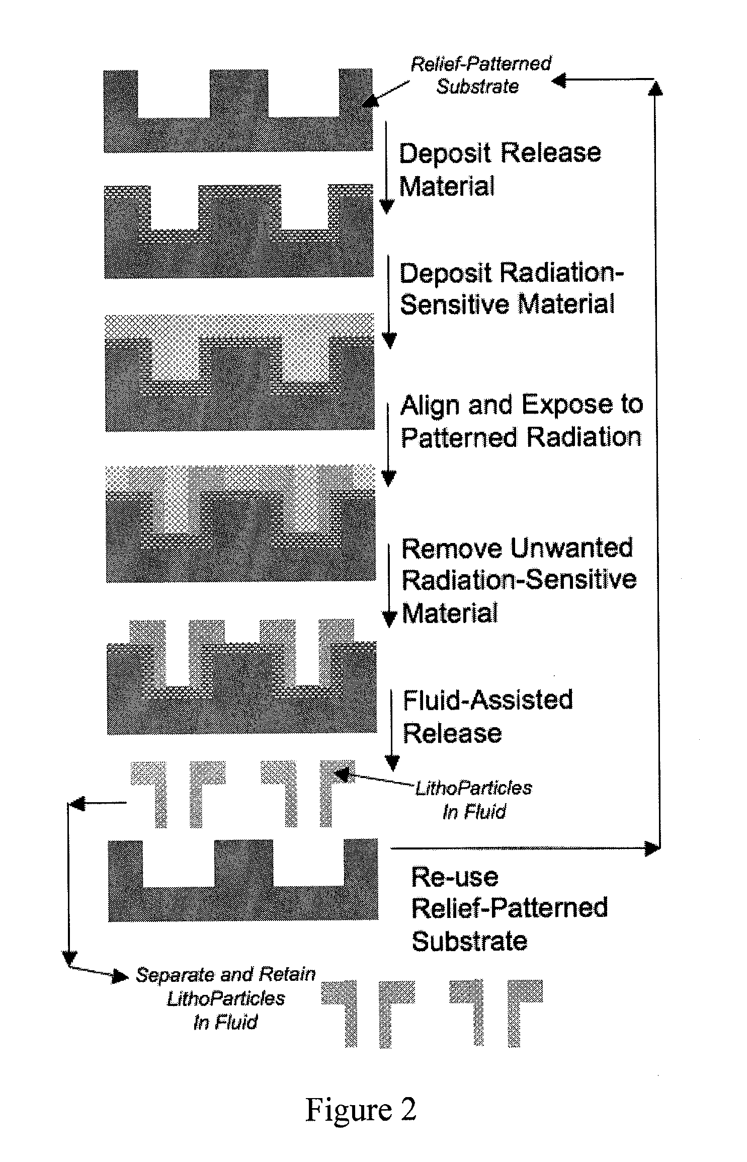
[0037]A process for mass-producing a plurality of particles using relief radiation templating according to an embodiment of the invention is as follows:
Phase I: Design and Fabricate a Relief Template and a Mask for Spatially Patterned Radiation Based on Desired Particle Shape.
[0038]A relief template can be created by standard lithographic techniques as described in Hernandez, C. J.; Zhao, K.; Mason, T. G. Pillar-deposition particle templating: A high-throughput synthetic route for producing LithoParticles (Soft Materials 2007, 5, 1-11) and Hernandez, C. J.; Zhao, K.; Mason, T. G. Well-deposition particle templating: Rapid mass-production of LithoParticles without mechanical imprinting (Soft Materials 2007, 5, 13-31). In one embodiment of the current invention, a relief template can essentially be a silicon wafer that has been patterned on its top surface using lithographic and etching processes. The pattern for the relief template, as well as the pattern for the radia...
second example embodiment
the RRT Process
[0062]A simple alternative method for making the LithoParticles using RRT involves permanently bonding a low-surface energy release agent to the surfaces of the relief template. This release agent can take the form of a fluorocarbon, fluorohydrocarbon, or fluoro-siloxane with appropriate reactive groups for bonding these molecules to a portion of the surfaces of the relief template. This type of low-surface energy coating can be applied using standard methods of surface treatment. After treating the relief template by coating and bonding a high surface density of such molecules to all of the patterned surfaces, the treated relief template surface will have only a very weak attractive interaction with a desired particle material. The permanent release coating permits facile fluid-assisted release of particles from the patterned surfaces of the relief template without the need for the fluid material to dissolve a sacrificial release layer. For instance, in an example em...
third example embodiment
the RRT Process
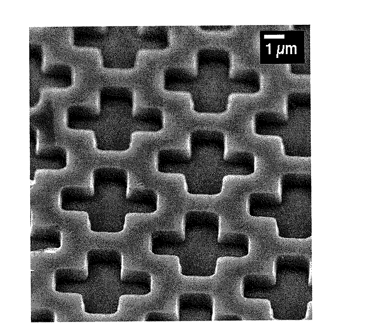
[0063]According to another embodiment of the current invention, a flat, polished silicon wafer, having a four-inch diameter and thickness of about 500 microns, is etched on one side to form a plurality of wells, each well has a shape of a square cross that is about 4.5 microns end-end length for the arms and each arm is about 1 micron wide. The depth of the wells is approximately one micron. The arrangement of the wells is in an array, where center-to-center positions of the crosses form a hexagonal lattice, as illustrated in FIG. 5. This patterned and etched wafer is the relief template (i.e. and is also referred to as the relief substrate).
[0064]A layer of release material is deposited onto the relief template. In this example, the release material is Omnicoat (from MicroChem Inc.), and, after it has been deposited as a thin solid layer, it can be dissolved in an aqueous solution that has a pH adjusted according to instructions of the manufacturer. The purpose of th...
PUM
| Property | Measurement | Unit |
|---|---|---|
| Length | aaaaa | aaaaa |
| Temperature | aaaaa | aaaaa |
| Chemical properties | aaaaa | aaaaa |
Abstract
Description
Claims
Application Information