Cao heat engine and refrigerator

a heat engine and refrigerator technology, applied in the field of heat engines, can solve the problems of heat engine serous dilemma, heat engine may have a larger size and lower mean effective pressure, and heat engine may have a large size, etc., and achieves the effect of increasing heat transfer duration, large power output, and increasing heat transfer duration

Inactive Publication Date: 2010-04-15
CAO YIDING
View PDF5 Cites 37 Cited by
  • Summary
  • Abstract
  • Description
  • Claims
  • Application Information

AI Technical Summary

Benefits of technology

[0016]It is therefore an objective of this invention to provide a heat engine using a gas as the working fluid and having a significantly increased heat transfer duration from a heat source to the working fluid without increasing the number of strokes per power stroke in a cycle. Said engine may be constructed based on the structure of a conventional combustion engine, such as a four-stroke piston-type combustion engine, a two-stroke piston-type combustion engine, a rotary combustion engine, or a free-piston type combustion engine. The heat engine is provided with at least a heating chamber per piston or rotor. Each said heating chamber has a heat exchanger unit disposed therewithin, and at least a port leading to a working chamber. Associated with said port a heating-chamber valve may be provided, which may open or close said port to establish or block the flow of the working fluid between said heating chamber and working chamber. Thereby the heat transfer duration is substantially increased between the working fluid and the heat source without increasing the number of strokes per power stroke in a cycle, and thereby many of the operational characteristics of an Otto power cycle may be attained in said heat engine and a sufficiently large power output with a reasonably high thermal efficiency may be achieved for the heat engine disclosed herein.
[0017]Another major objective of this invention is to provide a refrigerator using a gas or a two-phase mixture as the working fluid based on the basic structures of the various heat engines disclosed in this invention. The invention combines the compression functionality of a compressor and the expansion functionality of a turbine in an air cycle machine into a single refrigerator unit having a cooling means during the compression process. The invention also provides a significantly increased heat removal rate or duration before the expansion stroke to reduce the temperature of the working fluid without increasing the number of strokes per discharge stroke of the cooled working fluid in a cycle. In a preferred embodiment, said refrigerator is provided with at least a cooling chamber per piston or rotor. Each said cooling chamber has a heat exchanger unit disposed therewithin, and at least a port leading to a working chamber space. Associated with said port, a cooling-chamber valve may be provided, which may open or close said port to establish or block the flow of the working fluid between said cooling chamber and working chamber. Thereby the heat removal duration from the working fluid to a heat sink is substantially increased without increasing the number of strokes per discharge stroke of the cooled working fluid in a cycle, and thereby a sufficiently large cooling load with a reasonably high coefficient of performance may be achieved for the refrigerator disclosed herein.
[0018]Yet another objective of this invention is to provide a heat engine having a greater expansion ratio than the compression ratio. Said engine may incorporate a compression means such as a supercharger or turbocharger with an after cooler to accommodate the increased expansion ratio and to increase the power output of the engine while maintaining a relatively high thermal efficiency.
[0019]A further objective of this invention is to provide a refrigerator having a greater expansion ratio than the compression ratio. Said refrigerator may incorporate a compression means to accommodate the increased expansion ratio and to increase the coefficient of performance and the cooling load of the refrigerator.
[0020]In an embodiment associated with a heat engine, said heat engine based on the structure of a rotary engine or a piston engine may have a substantially increased heat transfer rate between the gaseous working fluid and the heat source through the employment of a heat pipe heat exchanger or a rotary regenerator.
[0021]In an embodiment associate with a refrigerator, said refrigerator based on the structure of a rotary heat engine or a piston heat engine may have a substantially increased heat removal rate between the working fluid and the heat sink through the employment of a heat pipe exchanger or a rotary regenerator.

Problems solved by technology

For a heat engine, however, the timing of the heat transfer through a heat exchanger may be difficult to control, and in many situations, this heat transfer may inevitably take place over the entire cycle not just near the top dead center, due to thermal inertia factors, such as that related to the mass of the heat exchanger walls.
Additionally, a heat engine may have a larger size and lower mean effective pressure in comparison with an internal combustion engine of comparable power output.
Additionally, because of the nature of heat acquisition by the working fluid through a heat exchanger, a heat engine may face a serous dilemma.
However, this lower compression ratio may result in a lower thermal efficiency of the heat engine, which may reduce the energy utilization rate from the heat source and at the same time also have a negative effect on the power output of the engine.
However, it is well known that many refrigerants used in vapor-compression refrigeration systems may have a negative environmental impact on global warming.
As may be known to those skilled in the art, a gas refrigeration system may have the disadvantages of an increased size and a higher mechanical frictional losses as compared to a vapor-compression refrigeration system utilizing evaporation / condensation phase-change processes for heat absorption and removal.

Method used


Image

  • Cao heat engine and refrigerator
  • Cao heat engine and refrigerator
  • Cao heat engine and refrigerator

Examples


Embodiment Construction

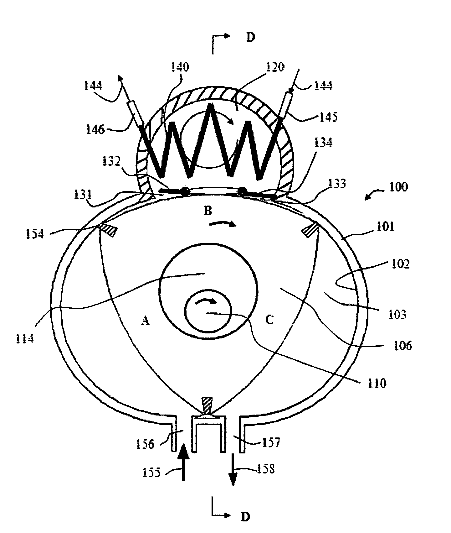
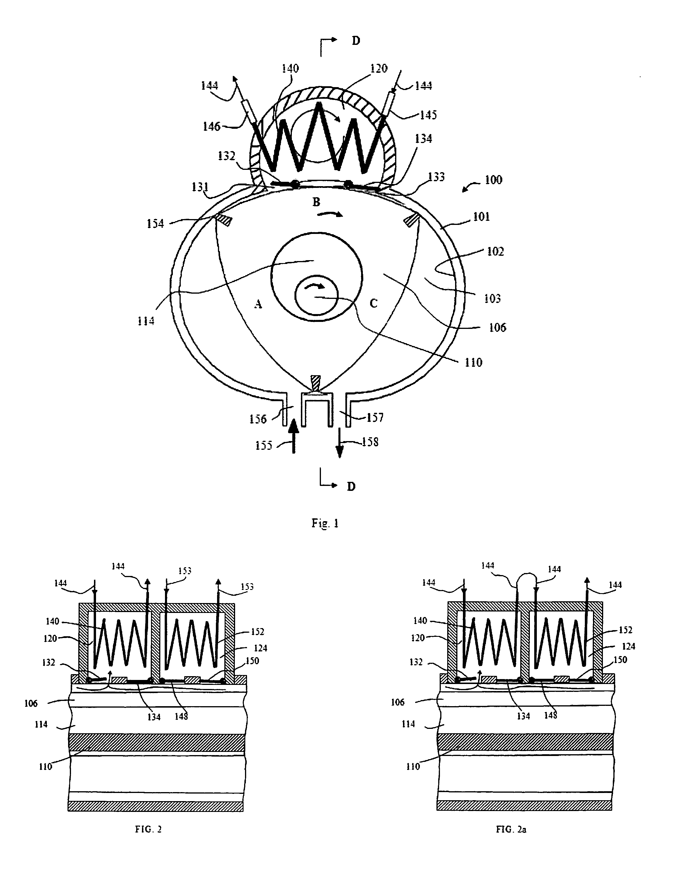
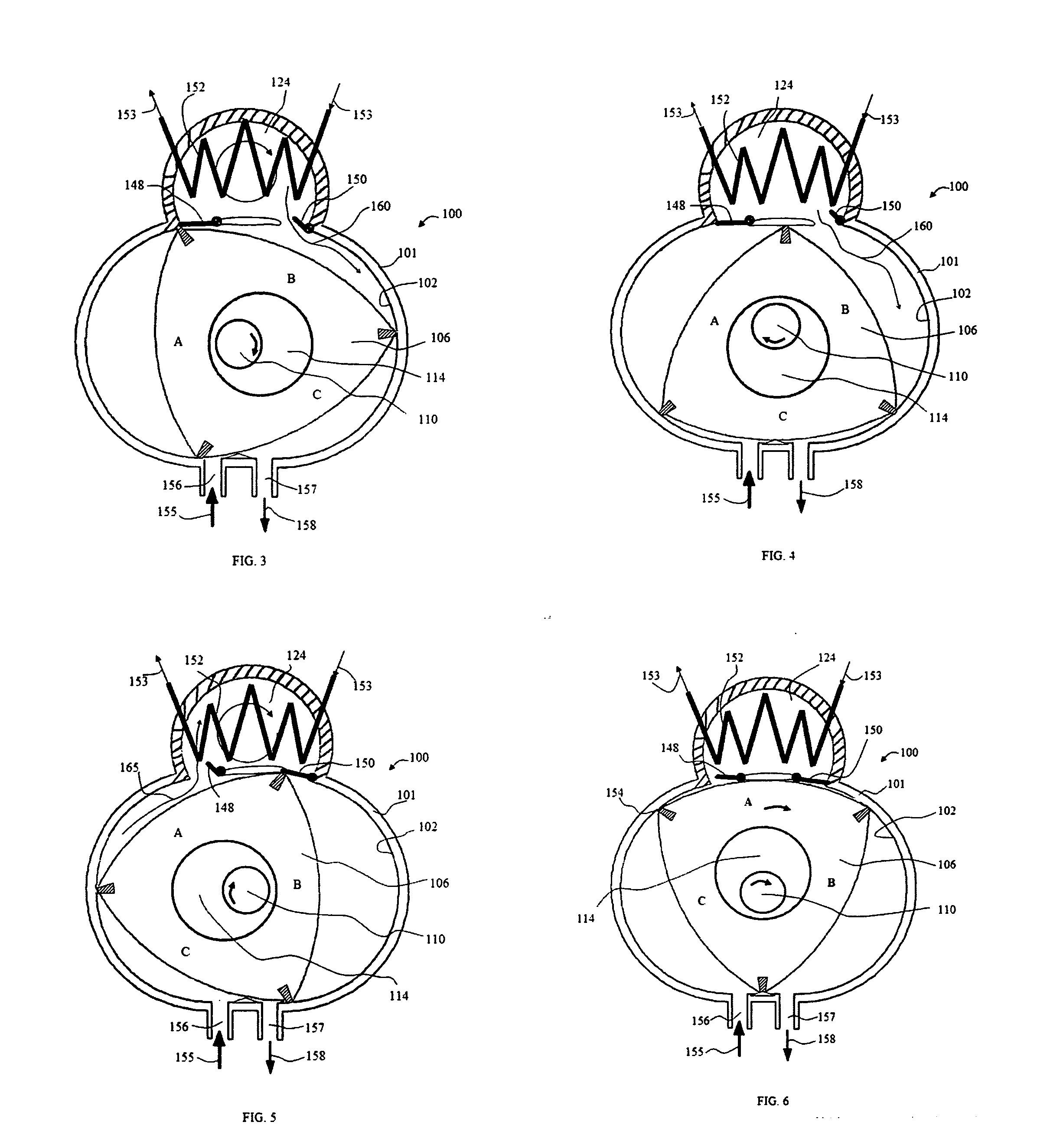
[0060]A rotary engine is an engine that may reproduce thermodynamic cycles of a piston-type combustion engine using a rotor instead of a reciprocating piston. One of the most well known rotary engines in use today is the Wankel-type rotary engine or Mazda rotary engine. The Wankel engine may reproduce the four strokes of the Otto engine or diesel engine using a triangular-like rotor moving around a nearly elliptical (epitrochoid) stationary housing. The combination of the eccentric shaft and “timing” gears causes the rotor to move around the housing with the three tips of the rotor being kept in contact with the side of the housing. The path that the rotor tips follow forms three separate working chambers between the three working faces of the rotor and the side of housing, whose volumes are constantly changing. Each of the three working chambers associated with a respective working face of the rotor may undergo a cycle including an intake stroke (or intake stage), a compression str...


PUM


Abstract

This invention provides heat engines based on various structures of internal combustion engines, such as a four-stroke piston-type combustion engine, two-stroke piston-type combustion engine, rotary combustion engine, or a free-piston type combustion engine. Said heat engine is provided with at least a heating chamber per piston or rotor, a heat exchanger unit disposed within said heating chamber through which thermal energy is extracted from a heat source and at least a port leading to a working chamber space from said heating chamber, and has a significantly increased heat transfer duration from the heat source to the working fluid within said heating chamber without increasing the number of strokes per power stroke in a cycle. Additionally, said heat engine is provided with an over expansion mechanism in conjunction with a compression means for intake charge. Thereby many of the operational characteristics of an Otto power cycle may be attained in said heat engine, and a heat source with a relatively low temperature may be accommodated through the combination of a lower compression ratio, the over expansion mechanism, and the boost of the intake charge.Another major objective of this invention is to provide a refrigerator based on the structures of the various heat engines disclosed in this invention and having a reversed operation of the heat engine. The invention combines the compression functionality of a compressor and the expansion functionality of a turbine in an air cycle machine into a single refrigerator unit having a simple mechanical structure, and provides a significantly increased heat removal rate or duration before the expansion stroke to reduce the temperature of the working fluid without increasing the number of strokes per discharge stroke of cooled working fluid in the cycle. Said refrigerator may include the over expansion mechanism or working fluid pressurization to increase the coefficient of performance and cooling load. In particular, said refrigerator uses a gas as the working fluid to avoid the negative impact of a conventional refrigerant on the environment.

Description

CROSS REFERENCES TO RELATED APPLICATIONS [0001]This application is a continuation of application Ser. No. 11 / 888,982 filed Aug. 4, 2007, and provisional patent application No. 61 / 195,283 filed Oct. 6, 2008.FIELD OF INVENTION [0002]This invention relates to heat engines that converts thermal energy from a heat source into mechanical work and relates to corresponding refrigerators having a reversed operation of the heat engines, in particular using a gas as the working fluid.BACKGROUND[0003]A heat engine is an energy system that performs conversion of thermal energy from an energy source or heat reservoir to mechanical work. A variety of energy sources may be employed to power the heat engine. These energy sources may include, but not limited to, solar energy, nuclear energy, geothermal energy, combustion gas from a combustion chamber, exhaust gas from a diesel engine, gasoline engine, or gas turbine engine, and flue gases and hot fluids from industrial furnaces or processes. Accordin...

Claims


Application Information

Patent Timeline
Patent Type & Authority Applications(United States)
IPC IPC(8): F02G1/00F25D9/00F03G6/00F02B53/00F01C1/04
CPCF01C1/22Y02E10/46F25B9/004F04B39/064
Inventor CAO, YIDING
Owner CAO YIDING
Why Eureka
Try Eureka