Hydragen-oxygen electrolyzing device and carbon paper electrodes thereof with material-changed outer surfaces

Inactive Publication Date: 2010-04-15
TROIKA INT +2
View PDF0 Cites 10 Cited by
  • Summary
  • Abstract
  • Description
  • Claims
  • Application Information

AI Technical Summary

Benefits of technology

[0007]The crux of the present invention is to improve the conventional hydrogen-oxygen el

Problems solved by technology

The ways to produce the hydrogen and the oxygen are versatile, but it is most environmentally protective and energy-conservative with electrolyzing.
If the gas films stagnantly aggregate on the surfaces of the electr

Method used


Image

  • Hydragen-oxygen electrolyzing device and carbon paper electrodes thereof with material-changed outer surfaces
  • Hydragen-oxygen electrolyzing device and carbon paper electrodes thereof with material-changed outer surfaces
  • Hydragen-oxygen electrolyzing device and carbon paper electrodes thereof with material-changed outer surfaces

Examples


first embodiment

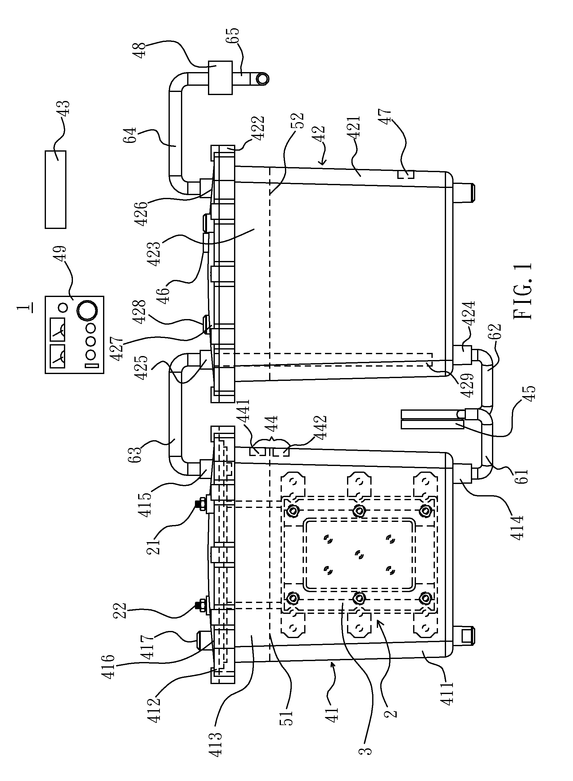
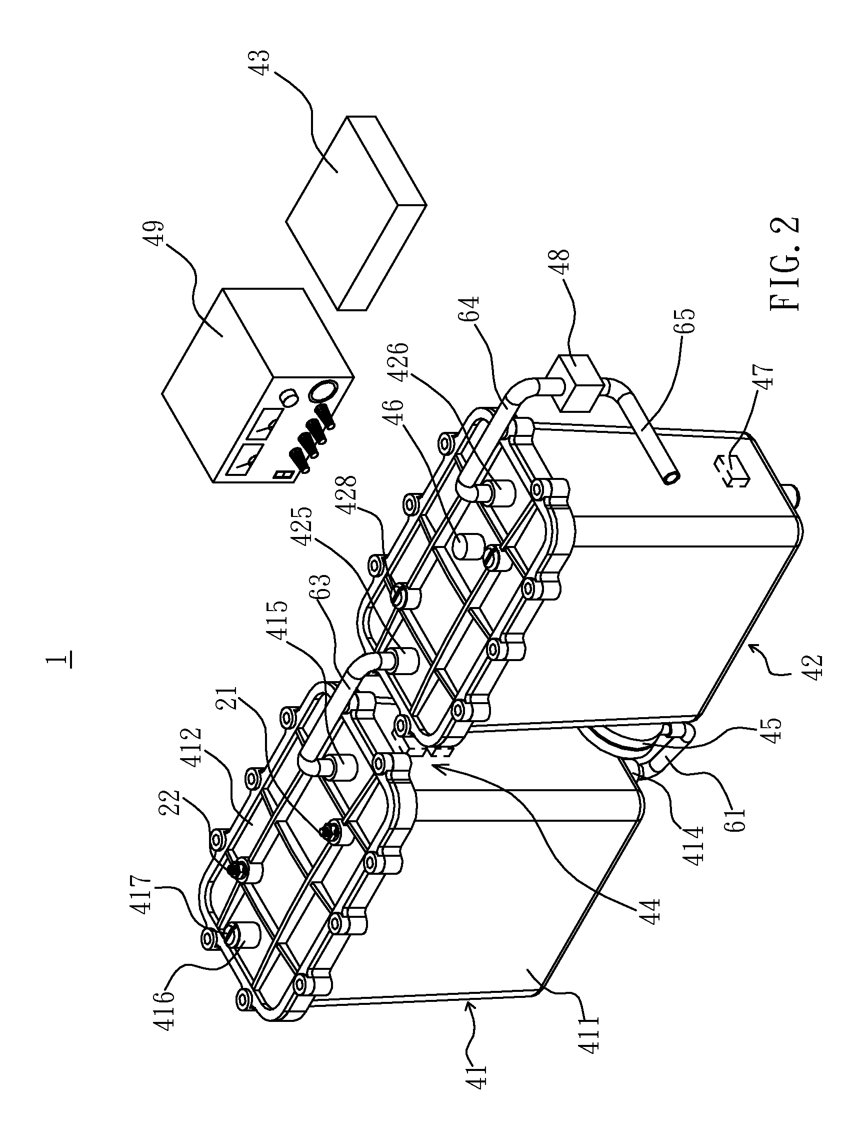
[0037]Referring to FIGS. 1 and 2, the hydrogen-oxygen electrolyzing device 1 of the first embodiment according to the present invention includes an electrolyzing structure 2, a first container 41, a second container 42, a controller 43, a level sensor 44, a pump 45, a gas pressure sensor 46, a second level sensor 47, an anti back fire valve 48 and a DC power supply 49. The electrical connections are prior art and the pump 45 can be a membrane pump.

[0038]Referring to FIG. 3, the first embodiment of the electrolyzing structure 2 includes a serial cell 3, a first conductor 21 and a second conductor 22. The serial cell 3 further includes a plurality of electrodes 20, a first frame 31, a second frame 32, a plurality of metal sheets 33, a plurality of insulating sheets 34, a plurality of insulating rods 35, a plurality of insulating pads 36, a plurality of insulating bolts 37 and a plurality of insulating nuts 38.

[0039]Referring to FIG. 4, each of the electrodes 20 is a carbon paper elect...

third embodiment

[0055]Referring to FIG. 7, a electrolyzing structure 7 in the third embodiment according to the present invention includes a plurality of serial cells 71, 72, 73, a first conductor 74, a second conductor 75 and a plurality of “U”-shaped third conductors 76. The serial cells 71, 72, 73 provide a structure of serial elongation in which the two serial cells 71, 72 are disposed at the two outermost sides of the electrolyzing structure 7. The structures of the serial cells 71, 72, 73 are the same as the electrode serial cell 3 shown in FIG. 3. The serial cells 71, 72, 73 each have a first frame 711, 721, 731 and a second frame 712, 722, 732 respectively; the first frames 711, 721, 731 have a first groove 713, 723, 733 respectively; the second frames 712, 722, 732 have a second groove 714, 724, 734 respectively; The serial cell 73 is disposed between the two serial cells 71, 72; the first frame 731 and the second frame 732 press against the second frame 712 and the first frame 721.

[0056]T...

fourth embodiment

[0057]Referring to FIG. 8, an electrolyzing structure provided in the fourth embodiment according to the present invention includes a plurality of serial cells 81, 82, 83, a first conductor 84 and a second conductor 85. The serial cells 81, 82, 83 constitute a structure of parallel extension with the two serial cells 81, 82 are disposed at the two outermost sides laterally.

[0058]The serial cells 81, 82, 83 each have a first frame 811, 821, 831 and a second frame 812, 822, 832, respectively; a plurality of metal sheets 813 and a plurality of insulation sheets 824 are disposed between the two lateral sides of both the first frame 811 and the second frame 812 respectively. The groove 815 of the first frame 811 is joined to the first conductor 84; the groove 825 of the second frame 822 is joined to the second conductor 85.

[0059]The structural arrangement for the serial cells 81, 82, 83 is the same as the serial cell 3 shown in FIG. 3, but the two first frames 811, 831 contact with the s...


PUM

PropertyMeasurementUnit
Diameteraaaaaaaaaa
Timeaaaaaaaaaa
Pressureaaaaaaaaaa

Abstract

A hydrogen-oxygen electrolyzing device for generating hydrogen and oxygen with electrolytic solution comprises a first container providing a receiving trough for containing the electrolyte, and at least an electrolyzing structure; the electrolyzing structure further comprises: at least a serial cell being disposed in the receiving trough and further comprising a plurality of electrodes with a gap between every two neighboring electrodes, a first conductor and a second conductor; the first and second conductors electrically connect with the two outermost electrodes; characterized in that each of the electrodes is a carbon paper electrode with both outer surfaces thereof being changed in material; the carbon paper electrode further comprises: a carbon paper substrate having a first surface and a second surface, a first metal layer being joined to the first surface, and a second metal layer being joined to the second surface.

Description

BACKGROUND OF THE INVENTION[0001]1. Field of the Invention[0002]The present invention is related to a hydrogen-oxygen electrolyzing device and particularly to a hydrogen-oxygen electrolyzing device and carbon paper electrodes each thereof with material changed outer surfaces.[0003]2. Brief Description of Related Art[0004]The District of Energy (DOE) of United States has changed the regulation regarding the electrolyzing efficiency of the water being electrolyzed as the hydrogen and the oxygen from current 45% to 75%, and the change will be in effect since 2010. The ways to produce the hydrogen and the oxygen are versatile, but it is most environmentally protective and energy-conservative with electrolyzing. Therefore, it is an extremely important goal to cooperate with the resource of renewable energy such as the wind power plant and the solar power plant to covert the water to the hydrogen and the oxygen as the storage energy effectively.[0005]The electrolyzing structure in the cur...

Claims


Application Information

Patent Timeline
IPC IPC(8): C25B9/16C25B1/06C25B9/06C25B9/17
CPCC25B1/08C25B9/203C25B11/0442Y02E60/50C25B15/00H01M8/0234Y02E60/366C25B11/12Y02E60/36C25B1/04C25B9/73C25B9/75C25B11/036C25B11/073C25B11/043
Inventor CHANG, CHAO
Owner TROIKA INT
Why Eureka
Try Eureka