Siphon tube for a multi-chamber fluid reservoir

a fluid reservoir and siphon tube technology, applied in the direction of machines/engines, containers, transportation items, etc., can solve the problems of high undesirable, partial vacuum, and the volume of fixed mass of coolant media will expand proportionally

Inactive Publication Date: 2010-04-15
MANN HUMMEL GMBH
View PDF2 Cites 16 Cited by
  • Summary
  • Abstract
  • Description
  • Claims
  • Application Information

AI Technical Summary

Benefits of technology

[0011]In one aspect of the invention, a multi-chamber reservoir for fluid includes both an upper reservoir body and a lower reservoir body. The bodies are configured for welding together to define a unitary fluid reservoir apparatus having a plurality of closed fluid chambers therein, including a pressure chamber and an overflow chamber. A pressure relief device is interposed in a fluid flow path between the pressure chamber and the overflow chamber. The fluid flow path includes a first passage extending between the pressure chamber and the relief device and a second passage extending between the relief device and the overflow chamber. Also provided is a siphon tube designed for snap-in mounting into the lower reservoir body. The siphon tube includes a fluid discharge opening, generally positioned near the bottom end of the siphon tube in a region near...

Problems solved by technology

A well known problem with closed loop coolant systems is that the volume of a fixed mass of coolant media will expand proportionally to the rise in coolant temperature.
This, of course, is highly undesirable.
This contraction in fluid volume results in a partial vacuum in the cooling system and leads to the creation of empty voids or air pockets within the cooling system.
The presence of entrained gas bubbles in the coolant fluid is undesirable as such gas bubbles reduce the efficiency of heat removal from the engine components, may become trapped in pockets inside the engine further reducing cooling, and is known to cause partial or...

Method used


Image

  • Siphon tube for a multi-chamber fluid reservoir
  • Siphon tube for a multi-chamber fluid reservoir
  • Siphon tube for a multi-chamber fluid reservoir

Examples


Embodiment Construction

[0023]The following detailed description is of the best currently contemplated modes of carrying out the invention. The description is not to be taken in a limiting sense, but is made merely for the purpose of illustrating the general principles of the invention, since the scope of the invention is best defined by the appended claims.

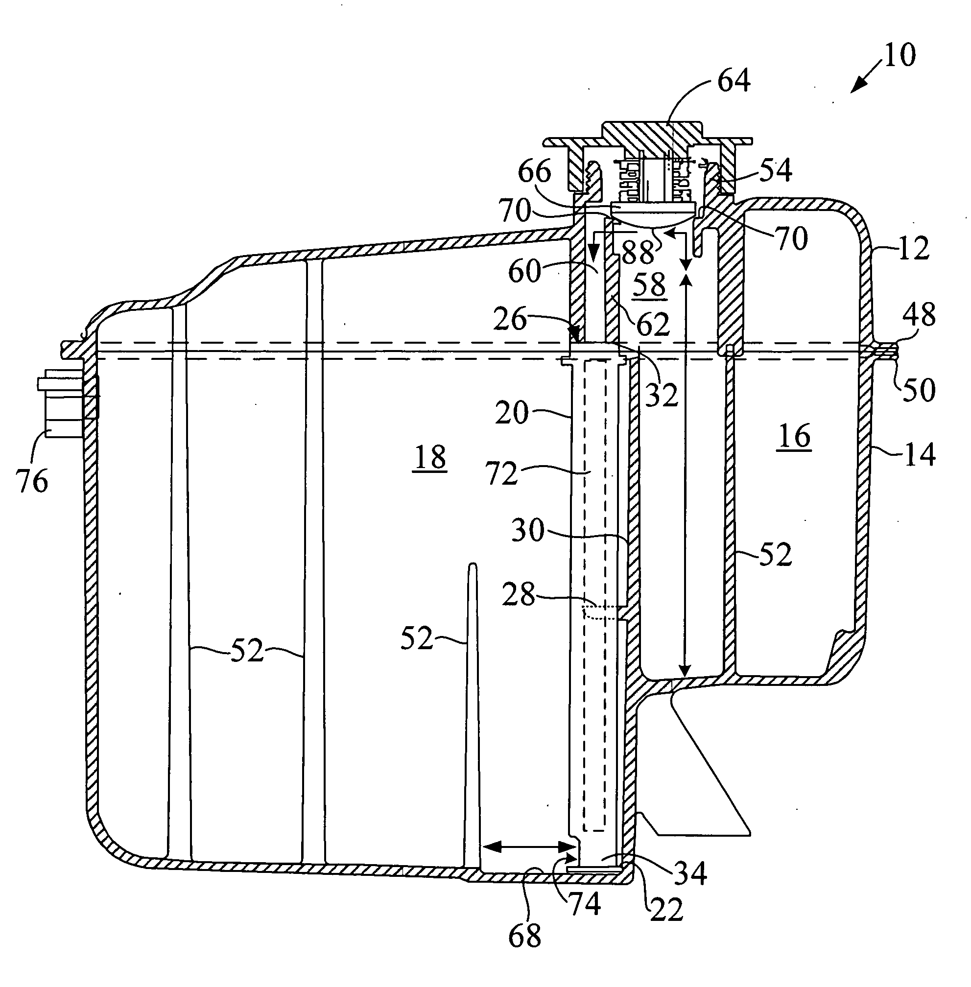
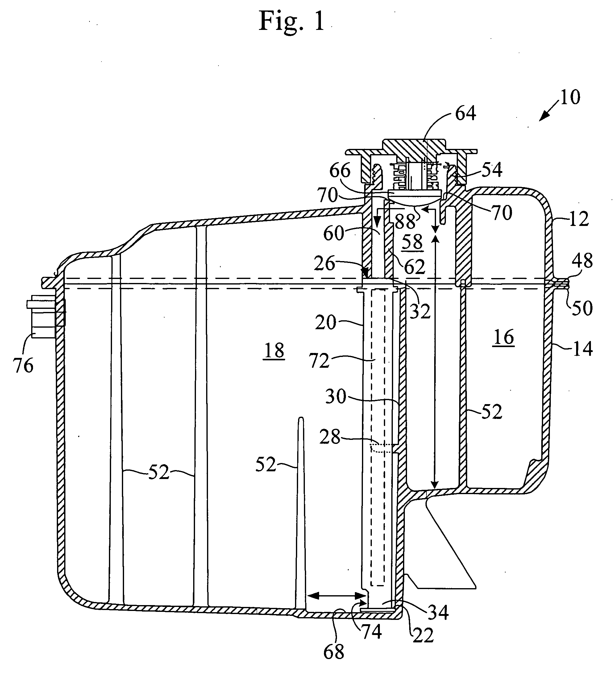
[0024]The present invention generally provides a multi-chamber fluid reservoir apparatus incorporating a separate siphon tube in a portion of the fluid flow path between two reservoir chambers. FIG. 1 illustrates a schematic sectional side view of one example embodiment of a multi-chamber reservoir apparatus 10 including a siphon tube 20, consistent with the present invention. In the illustrated embodiment, the multi-chamber reservoir apparatus 10 may be a combustion engine coolant reservoir such as for a motor vehicle (not shown).

[0025]In the illustrated embodiment, the multi-chamber reservoir body apparatus 10 is formed by the sealed closure of the up...


PUM


Abstract

A multi-chamber reservoir includes an upper and a lower body configured for welding into a unitary reservoir. A pressure relief device is interposed in a fluid flow path between a pressure chamber and the overflow chamber of the reservoir. A siphon tube designed for snap-in mounting into the reservoir is provided and includes an orientation feature for enforcing a desired alignment when mounting into the lower reservoir body together with a fluid discharge opening configured to deliver to and draw fluid from the overflow chamber near the bottom wall. A snap lock feature retentively mounts the siphon tube into the lower reservoir body and is adapted to hold the siphon tube in the desired alignment during the welding of the reservoir bodies. The snap lock feature enables the no-leak welding of the siphon tube to second passage during welding of the reservoir bodies, permitting this welding to be completed in one step.

Description

TECHNICAL FIELD[0001]The present invention generally relates to liquid coolant systems for internal combustion engines and, more specifically, to a multi-chamber coolant reservoir equipped with a siphon tube.BACKGROUND OF THE INVENTION[0002]Closed loop liquid coolant systems are frequently applied to remove heat that develops during the operation of internal combustion engines. A well known problem with closed loop coolant systems is that the volume of a fixed mass of coolant media will expand proportionally to the rise in coolant temperature. As the fluid capacity of the coolant recirculation system is fixed, this “excess” volume of coolant results in increasing internal pressure in the closed loop coolant system, eventually making it necessary to allow this “excess” coolant to escape to prevent overpressurization and failure of the cooling system. One quite old and well known solution is to allow this “excess” coolant to escape into the outside environment. This, of course, is hig...

Claims


Application Information

Patent Timeline
IPC IPC(8): B65D6/00
CPCF01P11/029Y10T137/86187Y10T137/86212Y10T137/86348
Inventor DEXTER, DAVID J.HEWKIN, DAVID
Owner MANN HUMMEL GMBH
Why Eureka
Try Eureka