
Vehicle airfoils for safety, efficiency, and performance

a technology for vehicles and airframes, applied in the field of airframes, can solve the problems of reducing vehicle mass, reducing rolling resistance as well as inertia, and limiting efforts to design lighter vehicles, so as to improve safety, efficiency, handling and performance of vehicles, and improve traction. the effect of traction

Inactive Publication Date: 2010-04-15
BECKON WILLIAM NELSON
View PDF11 Cites 71 Cited by
  • Summary
  • Abstract
  • Description
  • Claims
  • Application Information

AI Technical Summary

Benefits of technology

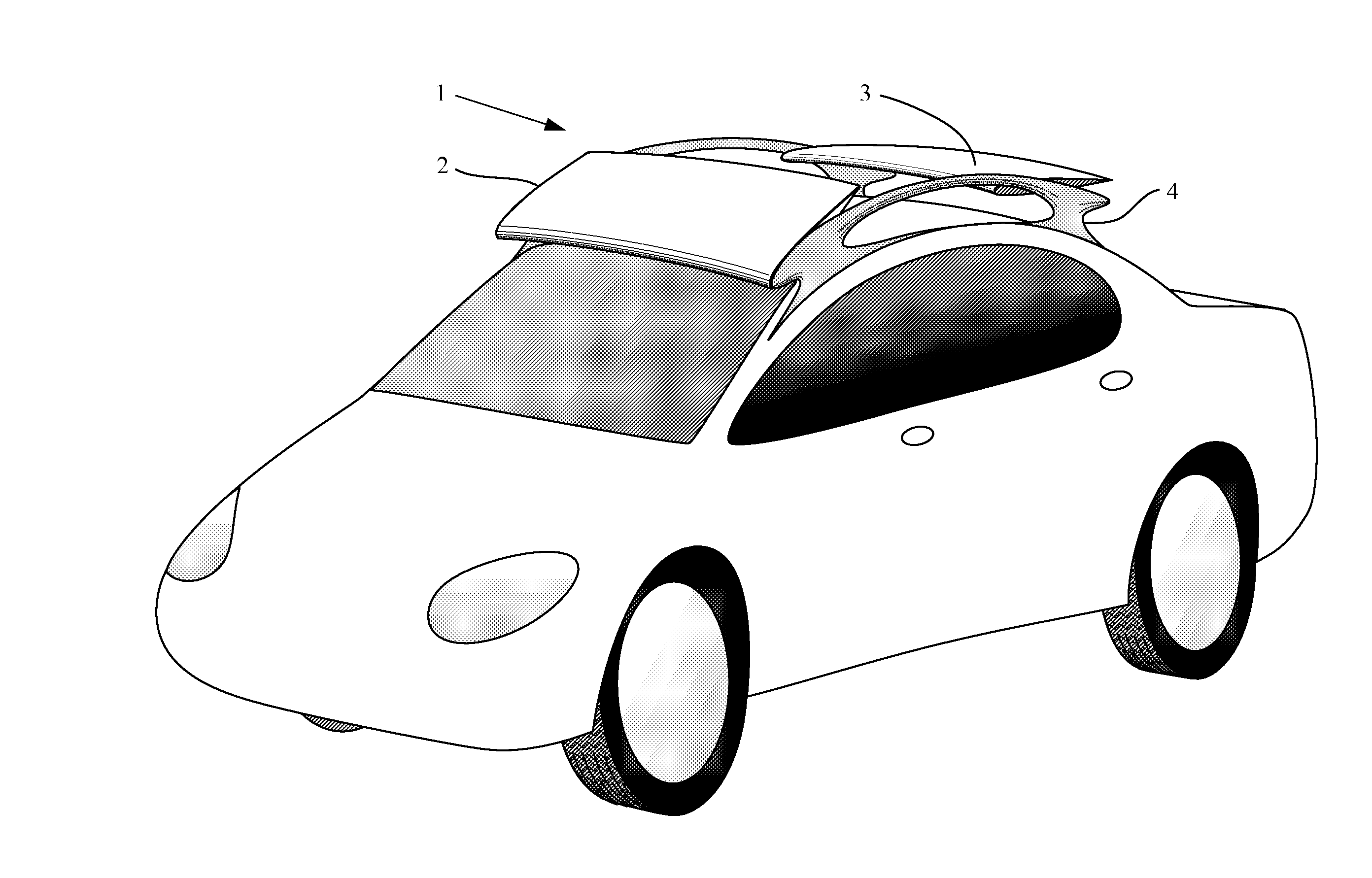
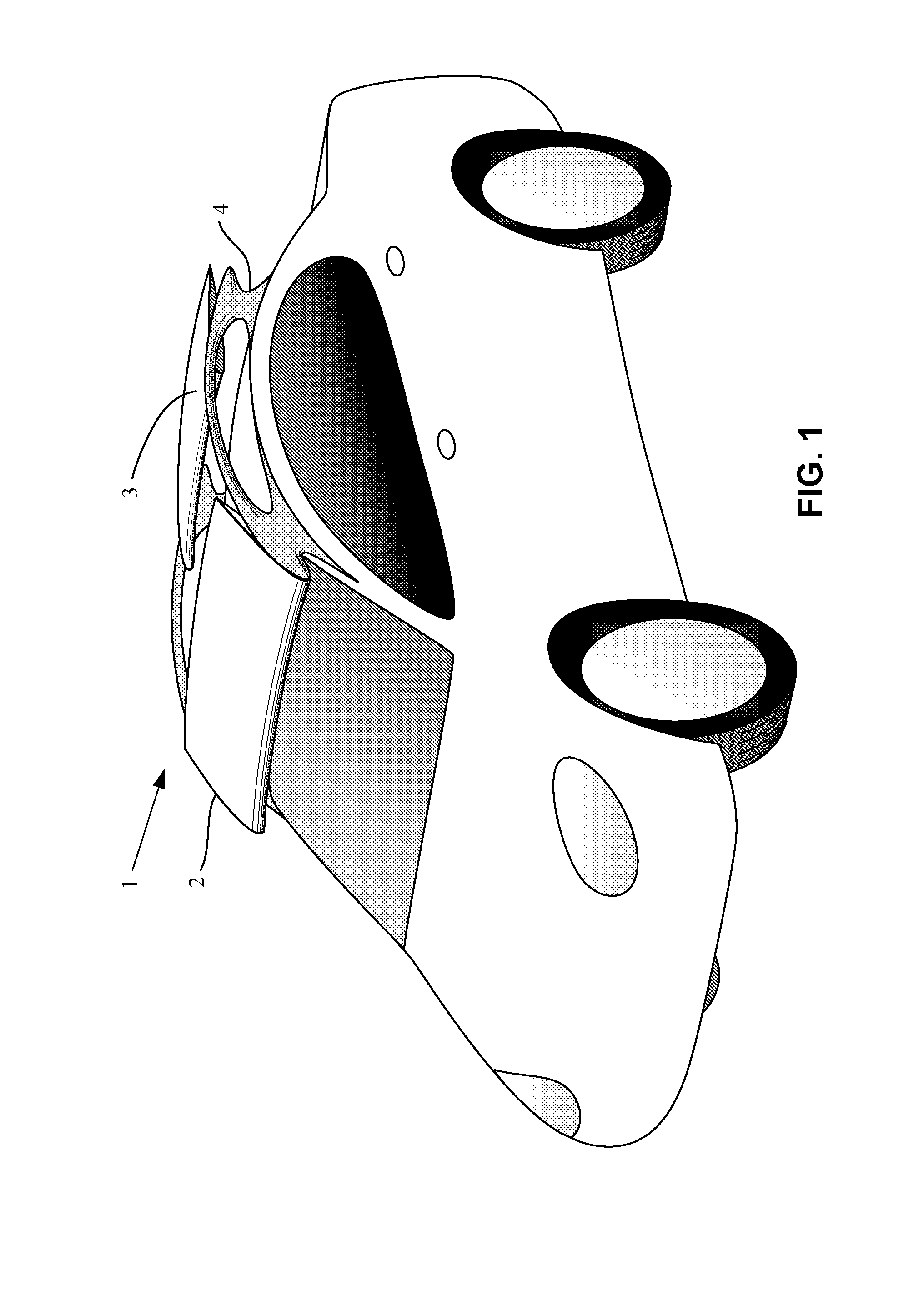
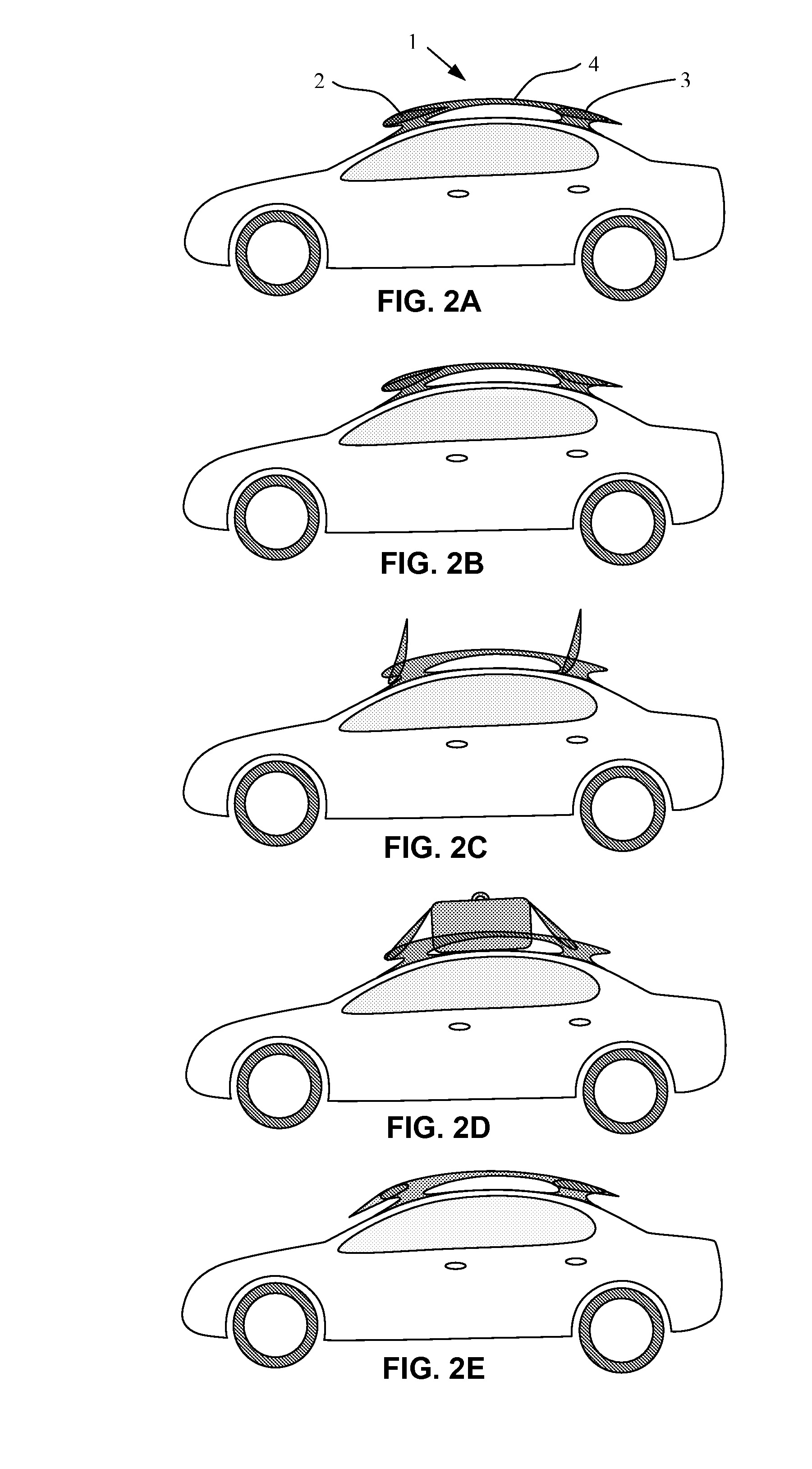
[0011]The primary purpose of the present invention is to use airfoils to improve the safety, efficiency, handling, and performance of vehicles, rectifying the deficiencies and reversing the dangerous effects of airfoils previously and currently employed on vehicles.
[0012]One or more airfoils are positioned substantially above the vehicle wheelbase. They provide down-thrust, well distributed over the vehicle wheels, increasing traction when additional traction is advantageous, such as during acceleration, braking, and turning. They also increase vehicle stability in crosswinds and turbulence. In preferred embodiments of the invention, the airfoils adaptively and automatically change angle of attack and / or camber, providing airbraking as well as strong down-thrust during strong braking and sharp turns, but alternatively providing lift when the vehicle is driven in a straight line at constant speed.

Problems solved by technology

Wheeled vehicle transportation accounts for a major portion of global energy consumption and contributes much of the pollution and greenhouse gases produced by the world.
Therefore, reduction in vehicle mass would reduce rolling resistance as well as inertia.
However, efforts to design lighter vehicles have been limited by handling and safety problems at high speeds because reduction in the weight pressing the wheels against the road results in less traction for accelerating, turning, and braking.
However, except at low speeds, rolling resistance would not be reduced.
Because most modern automobiles use the front wheels for propulsion a well as for steering and braking, wings in this location diminish automobile performance as well as safety, handling, and fuel efficiency.
Additionally, in this location, wings obstruct somewhat the rear view of the driver, further degrading safety.
In that location, restricted space and turbulent air flow among the steering, suspension and propulsion mechanisms of the vehicle severely constrain achievement of even the limited purposes of such fixed airfoils.
As with that patent, designs disclosed in other patents as well as airfoils actually installed on modern cars are generally fixed or may be adjustable, but are not designed to be under continuous adjustment by the driver or by some automatic system such as the vehicle computer.
However, in all configurations, this spoiler is designed to exert more or less down-thrust behind the rear wheels of the automobile, entailing all the safety, handling and efficiency problems noted above.

Method used


Image

  • Vehicle airfoils for safety, efficiency, and performance
  • Vehicle airfoils for safety, efficiency, and performance
  • Vehicle airfoils for safety, efficiency, and performance

Examples


Embodiment Construction

[0045]Most of the safety, performance and efficiency advantages of the present invention can be achieved by mounting a single airfoil (not illustrated) above the upper surface of a vehicle, substantially spanning the width of the vehicle and positioned approximately midway between the front and rear axles of the vehicle, or somewhat closer to the front wheels if the front wheels provide steering and propulsion in addition to braking. In the simplest embodiment of the invention, this airfoil has a fixed camber and angle of attack such that the airfoil exerts down-thrust at speed, making it possible for the vehicle to be constructed of low-density materials, such as aluminum and composites, without compromising safety and performance. Such a vehicle yields gains in efficiency due to reduced weight and therefore lowered rolling resistance at low speeds, and because a vehicle having less mass requires less energy to accelerate.

[0046]Additional improvements in efficiency can be achieved ...


PUM


Abstract

One or more airfoils, mounted above the upper surface of an automobile or other vehicle, optionally with variable angle of attack and / or camber, under the continuous automatic control of the vehicle's computer (electronic control module), for the purpose of providing well-distributed vertical thrust with minimum drag, or strong downward thrust with drag, depending on driving circumstances, thereby increasing the safety of the vehicle as well as improving its efficiency and performance.

Description

[0001]This invention was not made under federally sponsored research or development of any kind.REFERENCES CITED [0002]U.S. PATENT DOCUMENTS4,247,066January 1981Frost et al.244 / 2194,530,301July 1985Latham114 / 1025,419,608May 1995Takemoto296 / 180.16,045,096April 2000Rinn et al.244 / 2196,540,282 B2April 2003Pettey296 / 180.56,672,651June 2004Shuen296 / 180.57,114,456 B2October 2006Sohy114 / 102.227,213,870May 2007Williams296 / 180.17,226,117June 2007Preiss296 / 180.17,264,300September 2007Hillgaertner296 / 180.57,322,638 B2January 2008Larson296 / 180.5OTHER PUBLICATIONS[0003]Jacobs E N, Ward K E, Pinkerton R M. 1932. The characteristics of 78 related sections from tests in the variable-density wind tunnel. NACA Report. 460.[0004]National Research Council of the National Academies. 2006. Tires and Passenger Vehicle Fuel Economy: Informing Consumers, Improving Performance. Transportation Research Board Special Report 286.FIELD OF THE INVENTION[0005]This invention relates generally to airfoils mounted on...

Claims


Application Information

Patent Timeline
IPC IPC(8): B62D37/02E05F15/00B60Q1/26
CPCB60Q1/2661B60Q1/44B62D37/02B62D35/005B62D35/007B62D35/00
Inventor BECKON, WILLIAM NELSON
Owner BECKON WILLIAM NELSON
Learn More