Template synthesis for ecg/ppg based biometrics

a biometric and template technology, applied in the field of verification of the identity of individuals, can solve the problems of inability to create such an exhaustive set of features, inability to precisely determine the peak of the pqrst in an automated way, and uncertainty in the determination of the location

a biometric and template technology, applied in the field of verification of the identity of individuals, can solve the problems of inability to create such an exhaustive set of features, inability to precisely determine the peak of the pqrst in an automated way, and uncertainty in the determination of the location

US20100090798A1Inactive Publication Date: 2010-04-15KONINKLIJKE PHILIPS ELECTRONICS NV

Image

  • Template synthesis for ecg/ppg based biometrics
  • Template synthesis for ecg/ppg based biometrics
  • Template synthesis for ecg/ppg based biometrics

Examples


Embodiment Construction

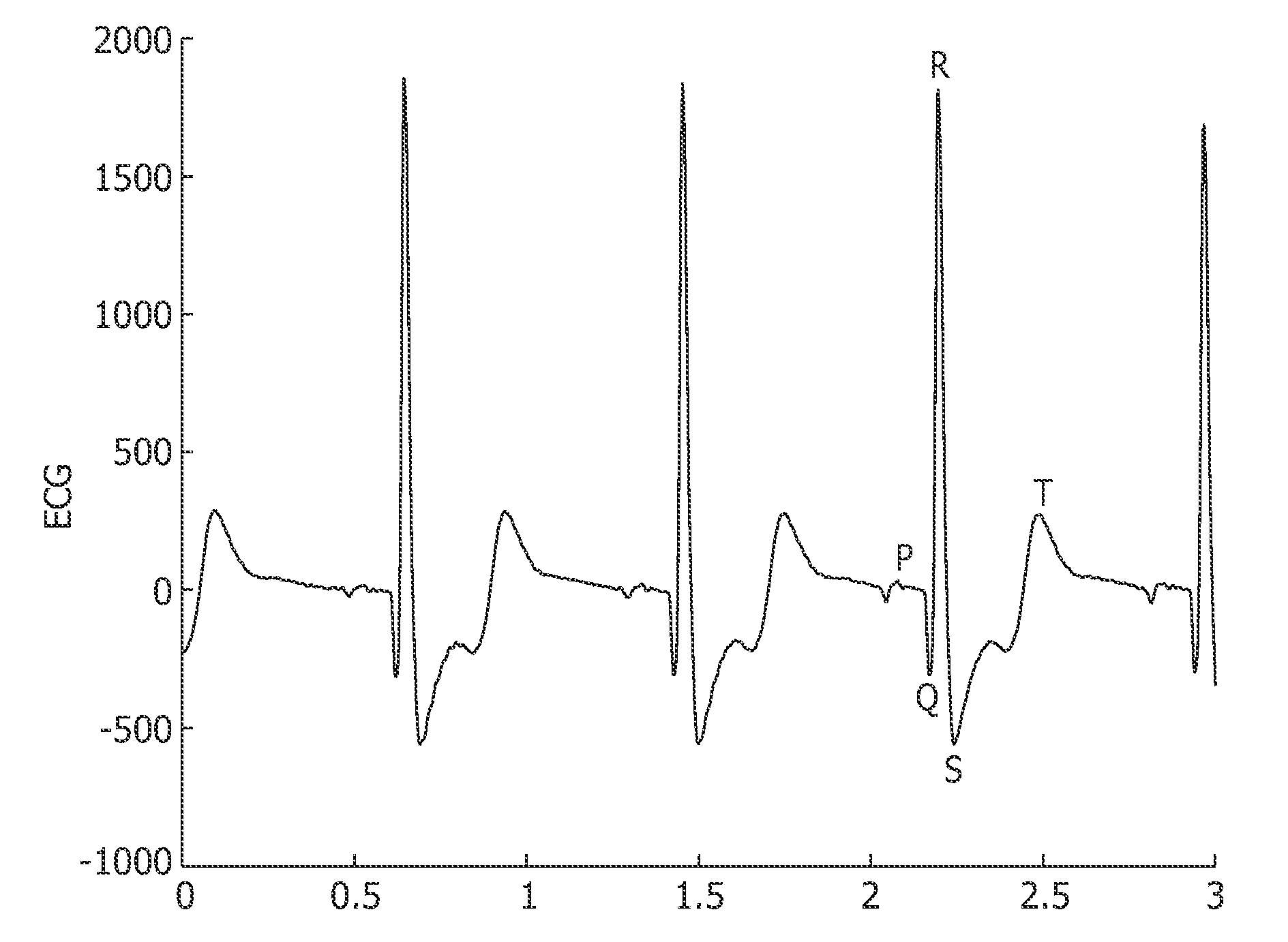
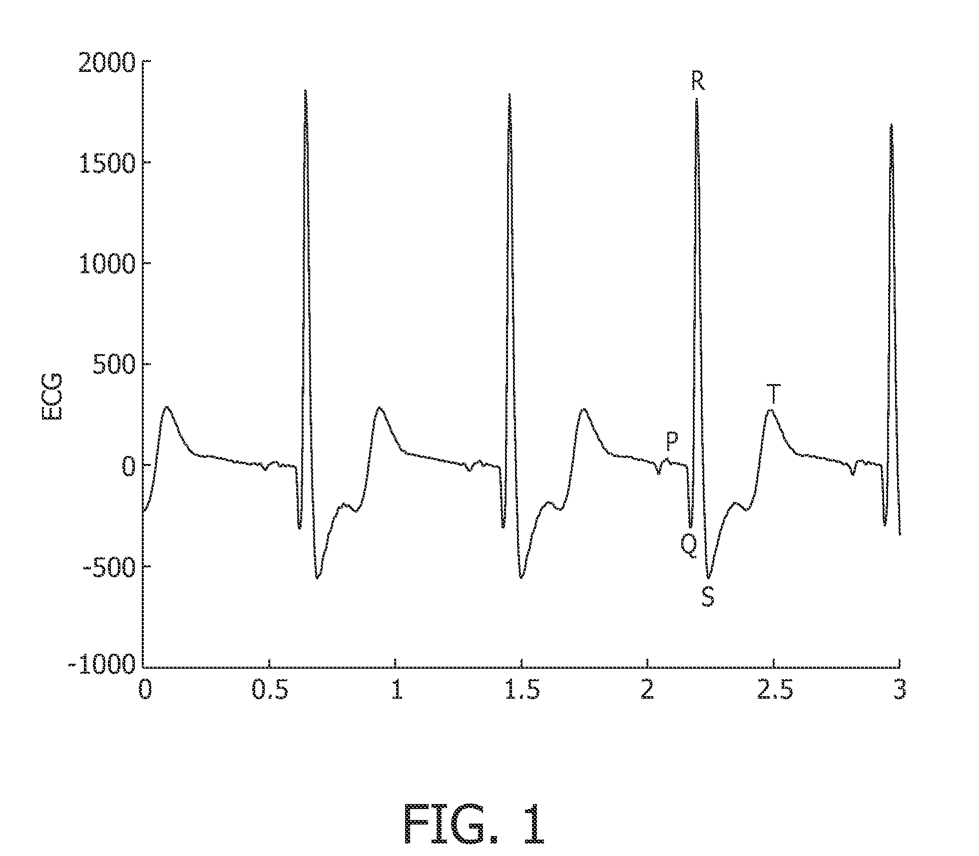
[0028]FIG. 1 shows an illustration of a recorded ECG, where a so called PQRST cycle has been indicated. As previously has been discussed, characteristics of PQRST cycles can be employed for extracting feature sets, or biometric templates, of an individual. Rather than determining the location of peaks in the PQRST cycle, shape of R-R segments can be used for biometric identification.

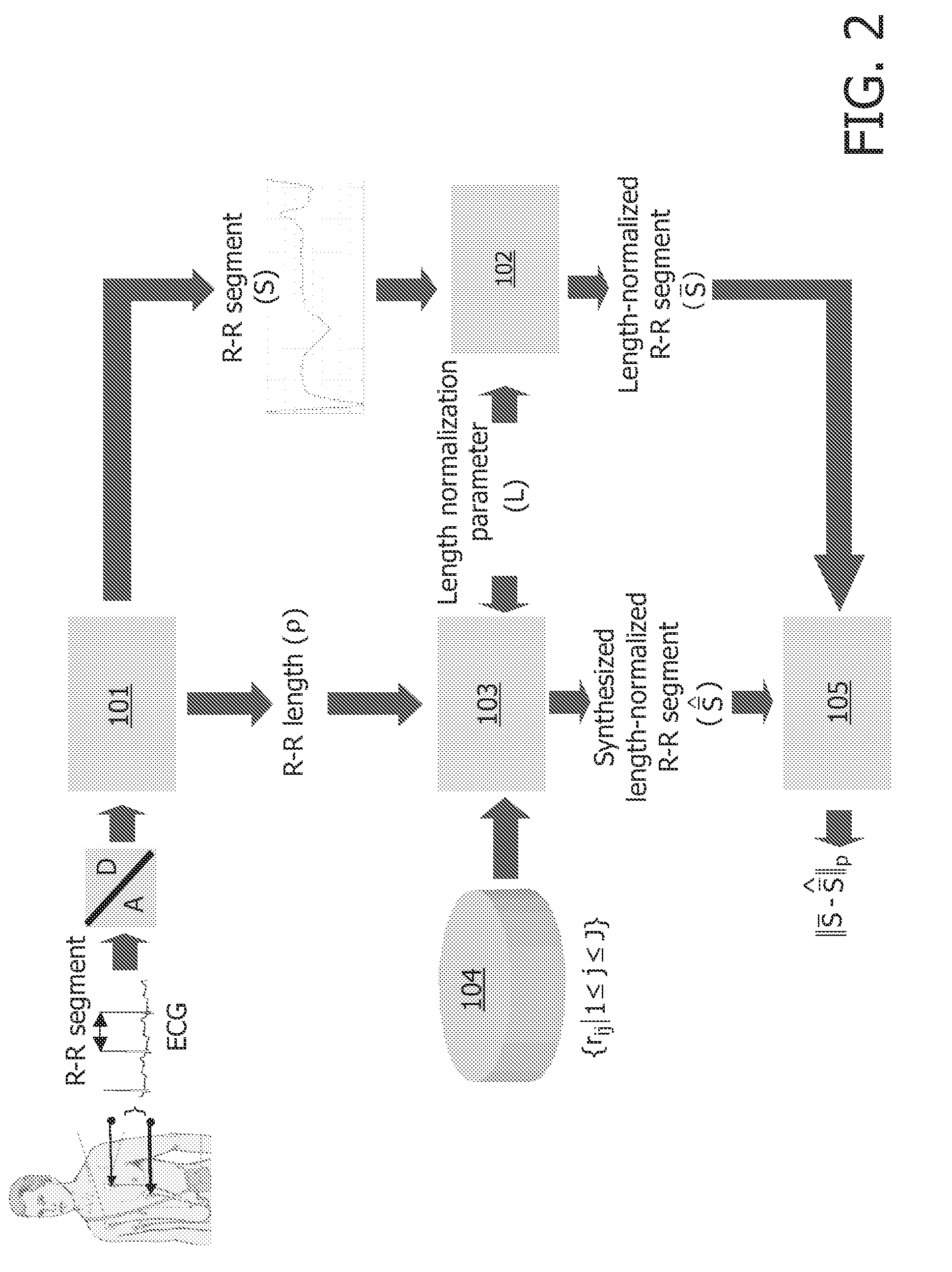
[0029]FIG. 2 shows a system for verifying identity of an individual in accordance with an embodiment of the invention. In the system, a digitized ECG signal is segmented by segmentation block 101. From the R-R segment S, the actual length ρ of the segment is derived. The R-R segment S is length-normalized to contain L samples by normalization block 102. L is thus referred to as the normalization parameter. In FIG. 2, the length-normalized R-R segment is output by normalization block 102 and denoted S. The length normalization parameter L is further used as input together with the actual length ρ of the R...


PUM


Abstract

The present invention relates to a method and a device for verifying identity of an individual by employing biometric data derived from a physical feature of the individual. A basic idea of the invention is that, rather than determining peak locations in cyclic signals such as ECG or PPG signals when using these signals as a representation of biometric data for verifying identity of an individual, shape or morphology of the signals is considered.

Description

TECHNICAL FIELD OF THE PRESENT INVENTION[0001]The present invention relates to a method and a device for verifying identity of an individual by employing biometric data derived from a physical feature of the individual.BACKGROUND ART[0002]Authentication of physical objects may be used in many applications, such as conditional access to secure buildings or conditional access to digital data (e.g. stored in a computer or removable storage media), or for identification purposes (e.g. for charging an identified individual for a particular activity).[0003]The use of biometrics for identification and / or authentication is to an ever-increasing extent considered to be a better alternative to traditional identification means such as passwords and pin-codes. The number of systems that require identification in the form of passwords / pin-codes is steadily increasing and, consequently, so is the number of passwords / pin-codes that a user of the systems must memorize. In biometric identification, ...

Claims


Application Information

Patent Timeline
15 Apr 2010
Publication
US20100090798A1
IPC
G06K9/00
CPC
G06K9/0055; G06K2009/00939; G06K9/6255; G06V40/15; G06F2218/16; G06F18/28
Inventors
GARCIA MOLINA, GARY NELSON; BRUEKERS, ALPHONS ANTONIUS MARIA LAMBERTUS