
Antenna Arrangement

Active Publication Date: 2010-04-15
NOKIA TECHNOLOGLES OY
View PDF24 Cites 13 Cited by
  • Summary
  • Abstract
  • Description
  • Claims
  • Application Information

AI Technical Summary

Benefits of technology

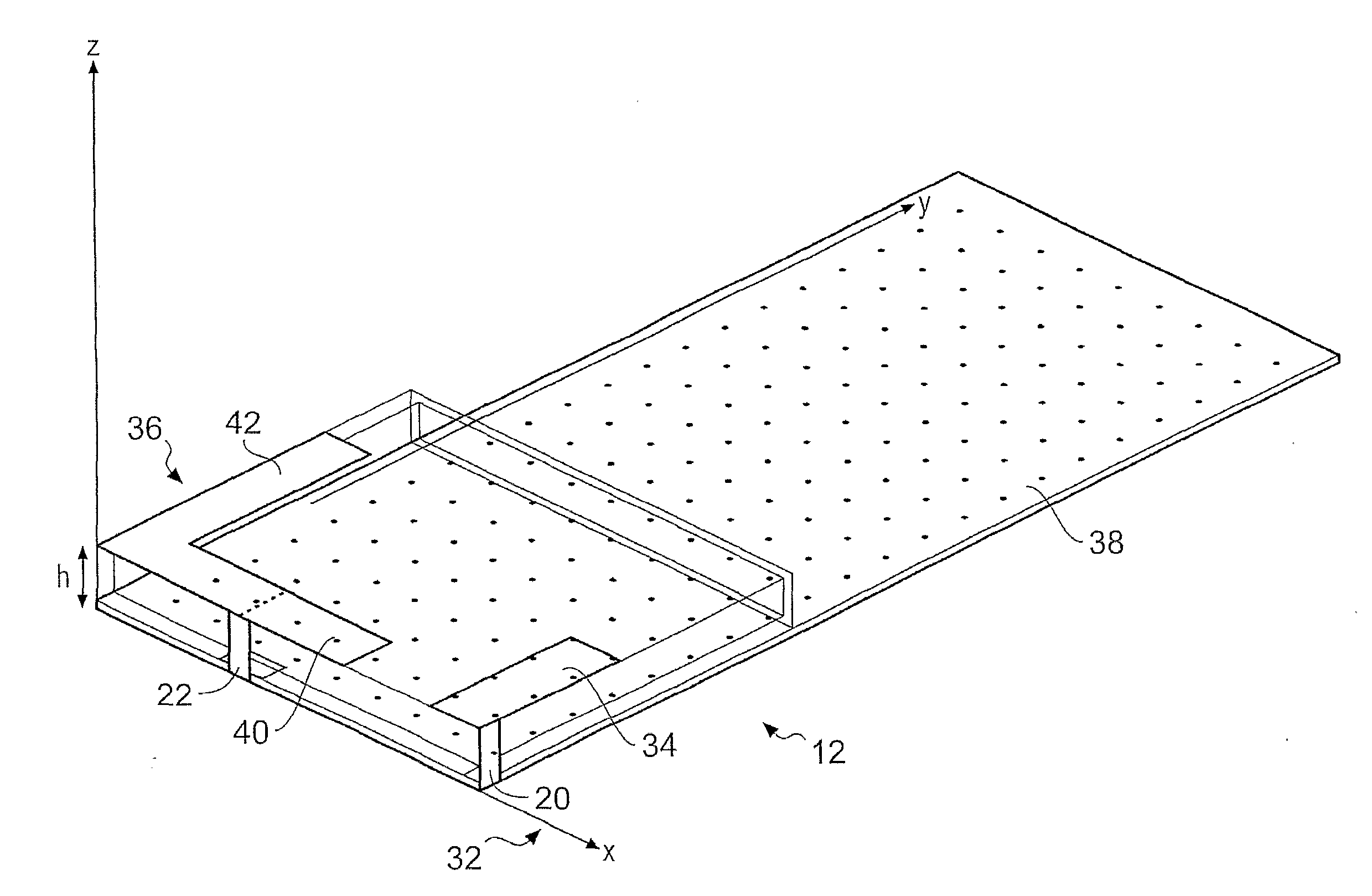
[0064]PILA's provide an advantage over PIFA's in embodiments of the present invention because when a PIFA operates as a parasitic element, its electrical length is not adjusted by its connected matching circuit. Since it is not possible to increase the electrical length of a PIFA when it is operating as a parasitic antenna by providing reactive elements in the matching circuit, the physical length of the PIFA may be greater than the physical length of a PILA at any given operating frequency. Therefore, one advantage provided by the first and second antenna elements 34, 36 being PILA's is that they may reduce the volume required for the antenna arrangement 12.

Problems solved by technology

However, the bandwidth of an antenna arrangement in such a device is usually affected by the size of the device.
However, tuneable loads increase the number of components in the device and may increase the cost of the device.

Method used


Image

  • Antenna Arrangement
  • Antenna Arrangement
  • Antenna Arrangement

Examples


first embodiment

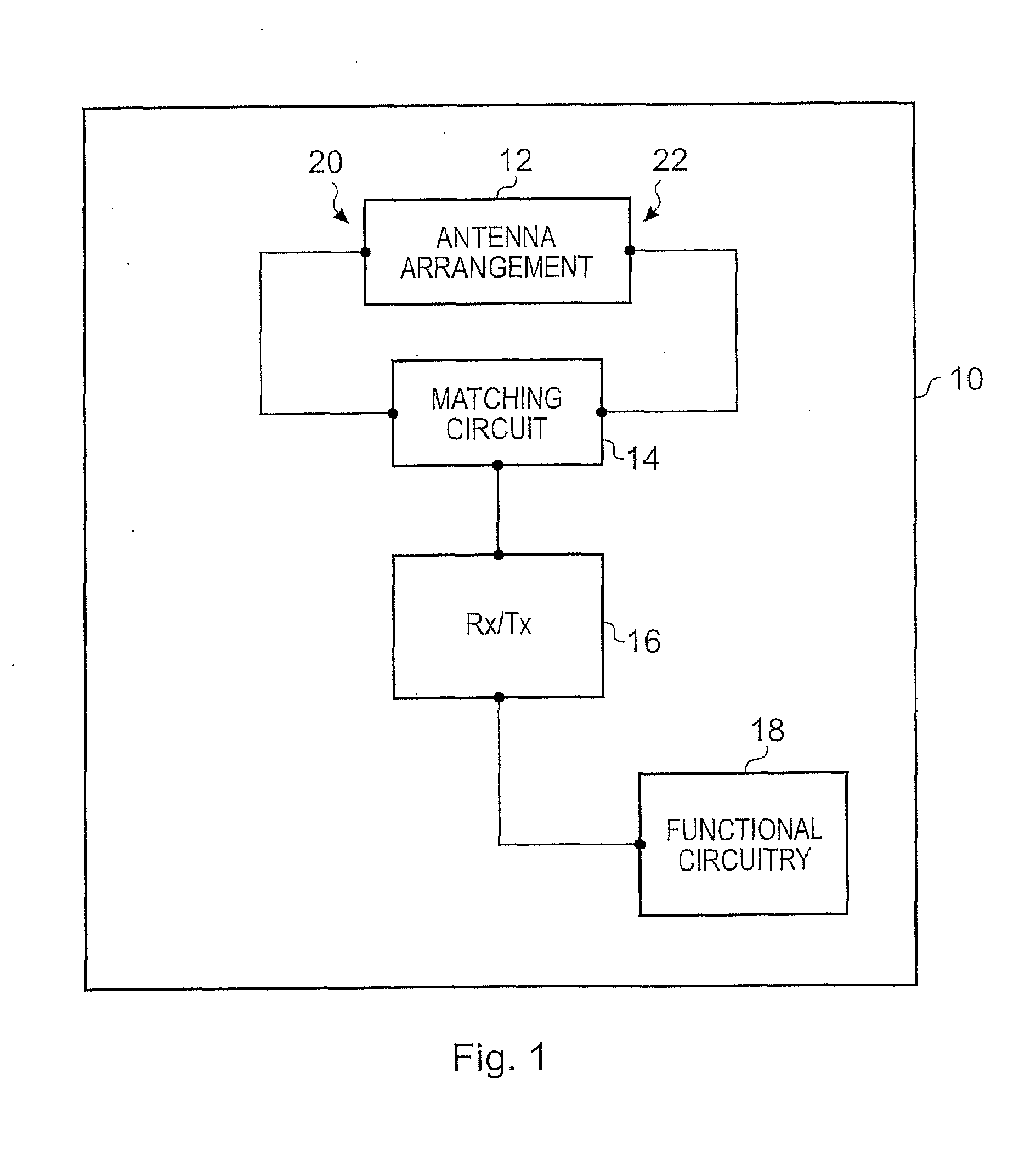
[0029]FIG. 1 illustrates a device 10 such as a portable electronic device (for example, a mobile cellular telephone), a cellular base station, other radio communication device or module for such devices according to the present invention.

[0030]The device 10 comprises an antenna arrangement 12, a matching circuit 14, a transceiver 16 and functional circuitry 18. The antenna arrangement 12 includes a first feed point 20 and a second feed point 22. The matching circuit 14 is connected to the first feed point 20, the second feed point 22 and to the transceiver 16. In one embodiment, the matching circuit 14 is a diplexer and matches the antenna arrangement to a single 50 ohm point. The functional circuitry 18 is connected to the transceiver 16 and is operable to provide signals to, and receive signals from the transceiver 16.

[0031]In the embodiment where the device 10 is a mobile cellular telephone, the functional circuitry 18 includes a processor, a memory and input / output devices such ...

second embodiment

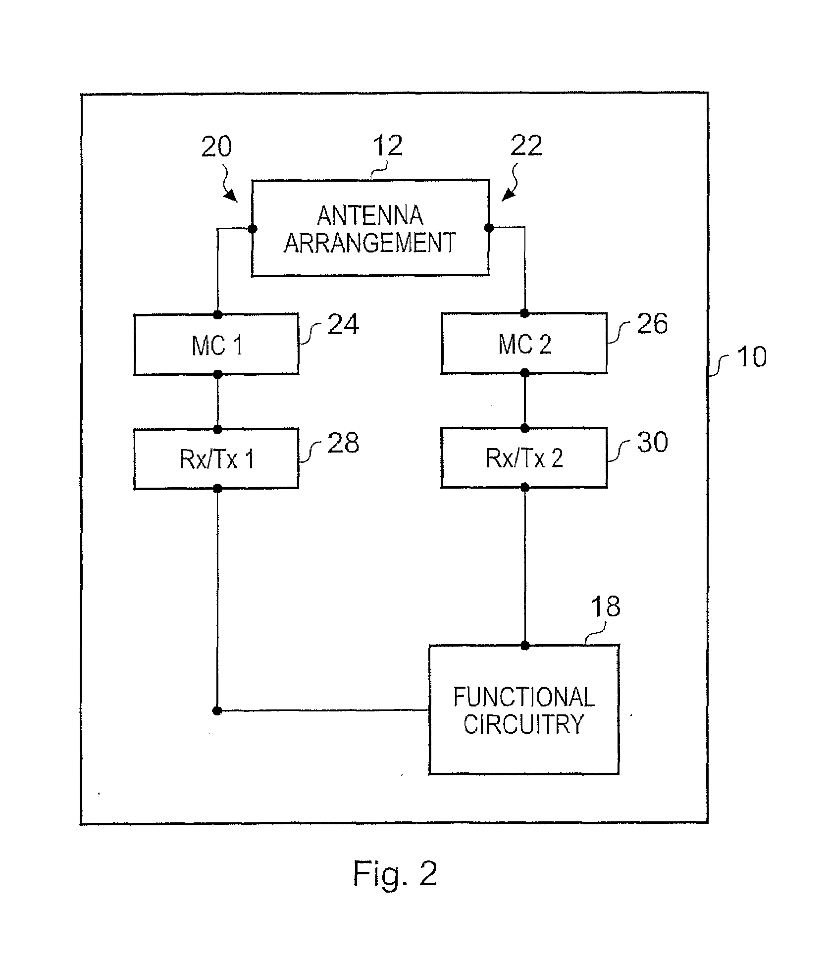
[0032]FIG. 2 illustrates a device 10 such as a portable electronic device (for example, a mobile cellular telephone), a cellular base station, other radio communication device or module for such devices according to the present invention.

[0033]The device 10 comprises an antenna arrangement 12, a first matching circuit 24, a second matching circuit 26, a first transceiver 28, a second transceiver 30 and functional circuitry 18. The antenna arrangement 12 includes a first feed point 20 and a second feed point 22. The first matching circuit 24 is connected to the first feed point 20 of the antenna arrangement 12 and to the first transceiver 28. The second matching circuit 26 is connected to the second feed point 22 of the antenna arrangement 12 and to the second transceiver 30. In one embodiment, the first and second matching circuits 24, 26 match the first and second feed points 20, 22 to 50 ohm points. The functional circuitry 18 is connected to the first transceiver 28 and to the se...


PUM


Abstract

An antenna arrangement including a first antenna element connected to a first feed point and having a first electrical length; a second antenna element connected to a second feed point, different to the first feed point, and including: a first portion which extends from the second feed point and has a second electrical length, similar to the first electrical length, which enables the first portion to electromagnetically couple with the first antenna element, and a second portion which extends from the second feed point and has a third electrical length, different to the first electrical length of the first antenna element and to the second electrical length of the first portion.

Description

FIELD OF THE INVENTION[0001]Embodiments of the present invention relate to an antenna arrangement. In particular, they relate to an antenna arrangement for a mobile cellular phone.BACKGROUND TO THE INVENTION[0002]In recent years, it has become desirable for radio communication devices to become smaller so that they may be carried more easily by a user. However, the bandwidth of an antenna arrangement in such a device is usually affected by the size of the device. Generally, the bandwidth of the antenna arrangement decreases as the size of the device is reduced. For example, the bandwidth of the antenna arrangement decreases if the dimensions of the ground plane (usually the printed wiring board of the device) are reduced, or if the height of the antenna arrangement above the ground plane is reduced.[0003]Currently, antenna arrangements are provided whereby each antenna is connected to a tuneable load which can shift the narrow bandwidth of each antenna to the correct operational fre...

Claims


Application Information

Patent Timeline
IPC IPC(8): H01Q1/38H01Q1/24
CPCH01Q1/243H01Q1/38H01Q21/30H01Q9/42H01Q9/40
Inventor ELLA, JUHA SAKARI
Owner NOKIA TECHNOLOGLES OY
Learn More