Complex type microscopic device

a microscopic device and complex technology, applied in the direction of material analysis using wave/particle radiation, instruments, nuclear engineering, etc., can solve the problems of difficult to properly observe an arbitrary portion of the image from the optical microscope, difficult to realize such a moving mechanism, and high cos

Inactive Publication Date: 2010-04-15
HORIBA LTD
View PDF1 Cites 24 Cited by
  • Summary
  • Abstract
  • Description
  • Claims
  • Application Information

AI Technical Summary

Benefits of technology

[0008]An object of the present invention is to provide a complex type microscopic device which can properly

Problems solved by technology

However, it is almost impossible to realize such a moving mechanism, and it would be extremely expensive even if it were realized.
However, there still remains a problem in the above complex type microscopic device that due to a large difference in magnification between the scanning electron microscope (20,000 to 30,000 times, for example) and the optical microscope (10 to 100 times, for example), in observing the same sample, an image observed at a magnification of the optical microscope and that observed at a magnification of the scann

Method used


Image

  • Complex type microscopic device
  • Complex type microscopic device
  • Complex type microscopic device

Examples


first embodiment

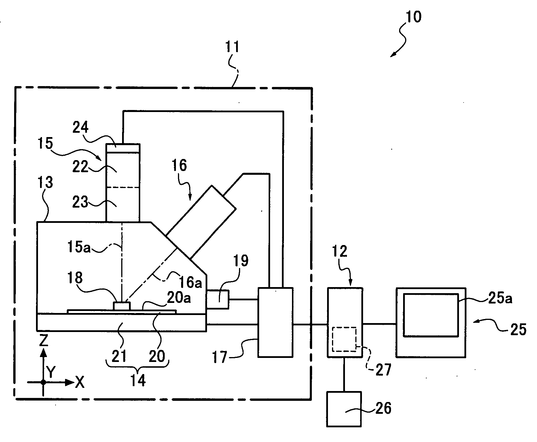
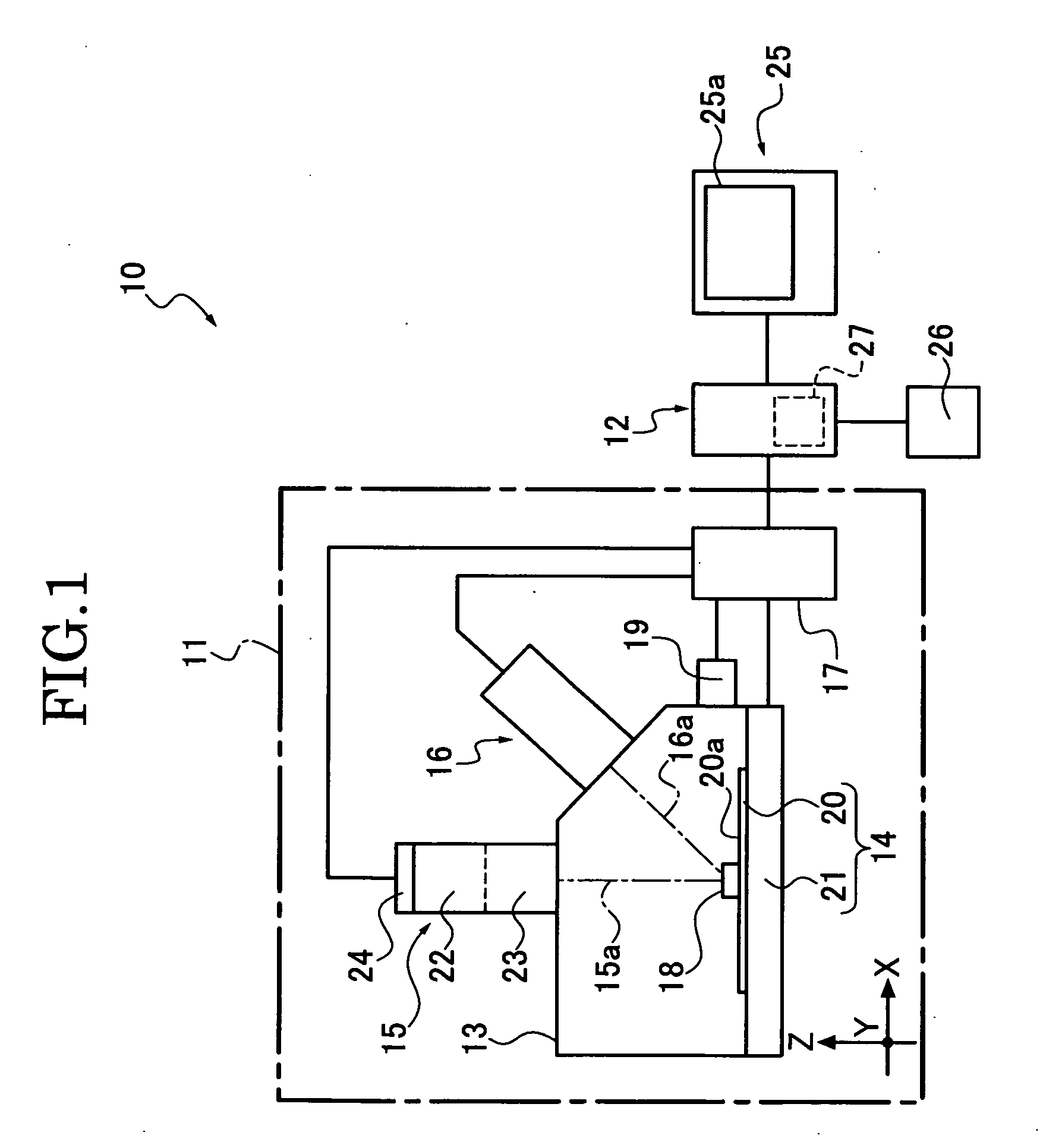
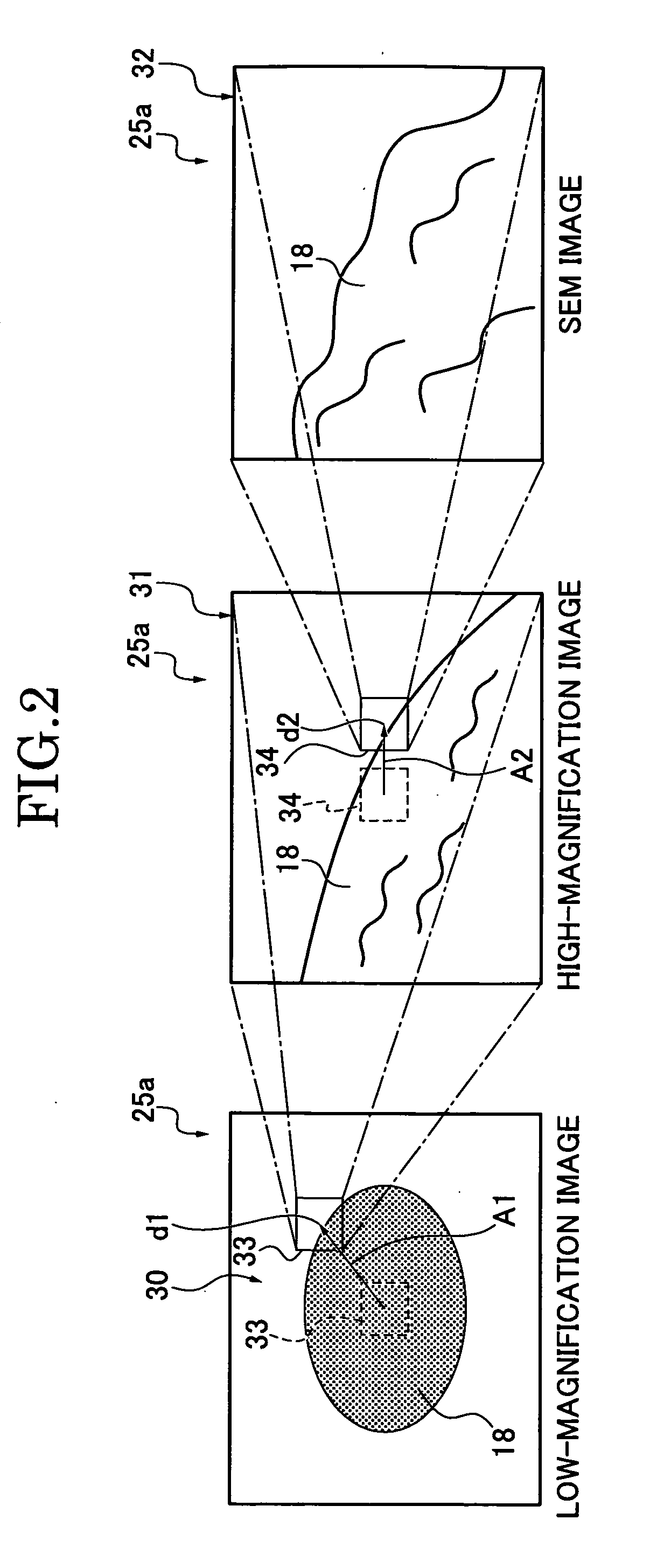
[0033]First, the basic structure and function of a complex type microscopic device according to the present embodiment will be described with reference to FIGS. 1 to 4. FIG. 1 schematically shows the structure of a complex type microscopic device 10. It is assumed that in FIG. 1, a horizontal direction is an X direction, a direction orthogonal to the X direction is a Y direction, and a direction orthogonal to an XY plane is a Z direction. FIG. 2 shows an image on a display screen 25a of the complex type microscopic device 10 and how the image display is changed. FIG. 3 shows another example of image display and a change of image display on the display screen 25a. FIG. 4 shows still another example of image display and a change of image display on the display screen 25a.

[0034]The complex type microscopic device is composed of a main unit 11 and a control unit 12 connected with the main unit 11. The main unit 11 comprises a specimen chamber 13, a slider unit 14, an optical axis 15a, ...

second embodiment

[0154]Now, another example of a complex type microscopic device according to the present embodiment will be described. A difference from the complex type microscopic device 10 is in the low-magnification frame and high-magnification frame displayed on the display screen 25a of the display unit 25. The basic structure of this complex type microscopic device is the same as that of the complex type microscopic device 10 so that the same components will be given the same numeric codes, and a detailed description thereon will be omitted.

[0155]In the present embodiment, the size of the low-magnification frame 33 is changeable on the low-magnification image 30, and so is the size of the high-magnification frame 34 on the high-magnification image 31 while in the first embodiment the size of the low-magnification frame 33 on the low-magnification image 30 is fixed to a certain size matching with an image observed at a magnification of the optical measurement / observation unit 23 and that of t...


PUM


Abstract

A complex type microscopic device includes a slider unit moving a stage, an optical microscope, a scanning electron microscope with an electron axis intersecting with an optical axis of the optical microscope, an optical measurement/observation unit having a magnification between those of the scanning electron microscope and the optical microscope and co-using an objective lens with the optical microscope, and a control unit controlling the entire device, and a display unit having a display screen. During display of a low-magnification optical microscopic image, the control unit controls the display unit to display, on the image, a representation to designate an area to be observed at a magnification of the optical measurement/observation unit, and to display, on the image, another representation to designate an area to be observed at a magnification of the scanning electron microscope during display of a high-magnification optical microscopic image.

Description

CROSS REFERENCE TO RELATED APPLICATION[0001]The present application is based on and claims priority from Japanese Patent Application No. 2008-266475, filed on Oct. 15, 2008, the disclosure of which is hereby incorporated by reference in its entirety.BACKGROUND OF THE INVENTION[0002]1. Field of the Invention[0003]The present invention relates to a complex type microscopic device incorporating a scanning electron microscope, and in particular to one which comprises a scanning electron microscope and a microscope having a different magnification but the same observing point from / as those of the scanning electron microscope.[0004]2. Description of the Related Art[0005]A complex type microscopic device for observing a part of an extremely minute sample has been known. For example, Japanese Unexamined Patent Application Publication No. Hei 06-308039 discloses a complex type microscopic device which comprises a foreign particle examining unit to observe a minute sample, a scanning electron...

Claims


Application Information

Patent Timeline
IPC IPC(8): G02B21/36G21K7/00
CPCG02B21/367H01J37/28H01J37/228H01J37/226
Inventor ISOZAKI, HISASHIOHTOMO, FUMIONUNOKAWA, KAZUO
Owner HORIBA LTD
Why Eureka
Try Eureka