Cold Row Encapsulation for Server Farm Cooling System

a cooling system and cold row technology, applied in the field of data center cooling systems, can solve the problems of increasing power consumption of servers, affecting the cooling efficiency of data centers, so as to reduce air leakage and reduce power consumption. the effect of cooling efficiency

Inactive Publication Date: 2010-04-15
R2 SOLUTIONS
View PDF46 Cites 28 Cited by
  • Summary
  • Abstract
  • Description
  • Claims
  • Application Information

AI Technical Summary

Benefits of technology

[0009]The present invention provides systems and methods directed to efficient cooling of data centers. In a particular embodiment, the present invention provides a cold row encapsulation structure comprising at least one server rack port configured to interface with one or more server racks and a cooling module connected to the top surface of the cold row encapsulation structure. The server rack ports are configured to engage the server racks such that a front face of the server racks interface with the interior space defined by the cold row encapsulation structure. In some embodiments, server racks ports and server racks are tightly connected by clamps and / or sealing gaskets to reduce air leakage into and out of the cold row encapsulation structure.

Problems solved by technology

While the performance of servers is improving, the power consumption of servers is also rising despite efforts in low power design of integrated circuits.
Processors are only part of a server, however; other parts in a server such as cooling fans and storage devices consume additional power.
As a result, server racks can produce very concentrated heat loads.
The heat collectively generated by densely populated racks can have an adverse effect on the performance and reliability of the equipment in the racks, since they rely on the surrounding air for cooling.
In addition to servers, CRAC units consume significant amounts of power as well.
The CRAC units collectively consume significant amounts of power in a data center.
However, since CRAC units are generally installed at the corners of the data center room, their ability to efficiently increase air flow rate is negatively impacted.
The cost of building a raised floor generally is high and the cooling efficiency generally is low due to inefficient air movement inside the data center room.
Removing tiles to fix hot spots can cause problems throughout the system.

Method used


Image

  • Cold Row Encapsulation for Server Farm Cooling System
  • Cold Row Encapsulation for Server Farm Cooling System
  • Cold Row Encapsulation for Server Farm Cooling System

Examples


Embodiment Construction

)

[0023]The following example embodiments and their aspects are described and illustrated in conjunction with apparatuses, methods, and systems which are meant to be illustrative examples, not limiting in scope.

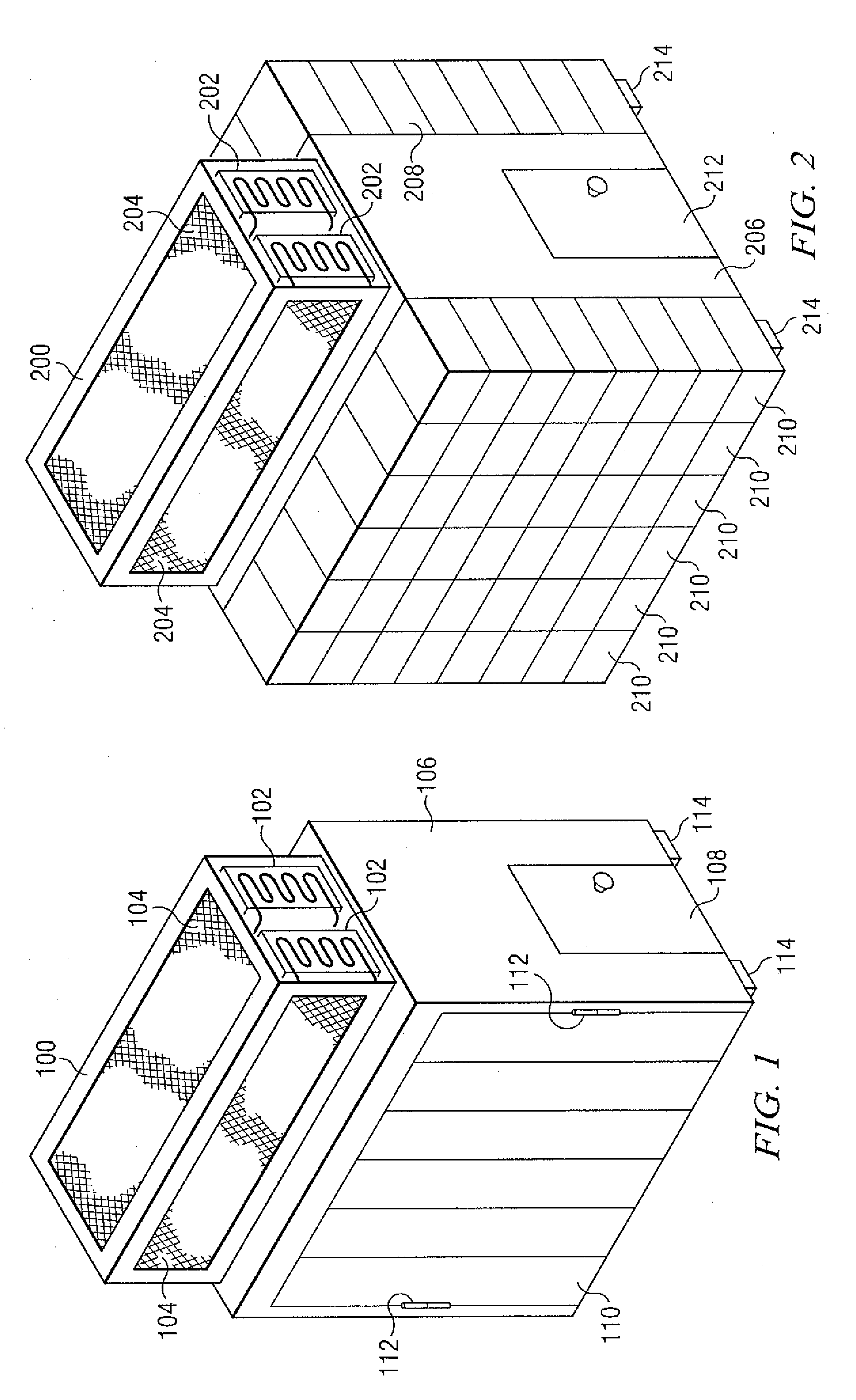
[0024]FIG. 1 illustrates an example cooling module 100 and an example cold row encapsulation structure 106. The cold row encapsulation structure 106 may have a frame, panels, doors, and server rack ports. A server rack port is an opening on the cold row encapsulation structure 106 that can be connected to a server rack. The cold row encapsulation structure 106 may be made of a variety of materials such as steel, composite materials, or carbon materials that create a housing defining an interior space including at least one server rack port that allows a rack-mounted unit to interface with the interior space. In some embodiments, the cold row encapsulation structure 106 may be mounted directly to the floor surface and no raised floor is required in a data center cooling room fo...


PUM


Abstract

Apparatuses, methods, and systems directed to efficient cooling of data centers. Some embodiments of the invention allow encapsulation of cold rows through an enclosure and allow server fans to draw cold air from the cold row encapsulation structure to cool servers installed on the server racks. In other particular embodiments, the systems disclosed can be used to mix outside cool air into the cold row encapsulation structure to cool the servers. In some embodiments, the present invention involves using multiple cold row encapsulation structures to cool the servers installed on the racks.

Description

CROSS REFERENCE TO RELATED APPLICATION[0001]The present application is a continuation of U.S. patent application Ser. No. 12 / 258,683 filed Oct. 27, 2008, which is incorporated by reference herein for all purposes. U.S. application Ser. No. 12 / 258,683 is a continuation of application Ser. No. 12 / 193,113 filed Aug. 18, 2008, which is incorporated by reference herein for all purposes. U.S. patent application Ser. No. 12 / 193,113 is a continuation of Ser. No. 11 / 757,864 filed Jun. 4, 2007, which is incorporated by reference herein for all purposes.TECHNICAL FIELD[0002]The present disclosure relates generally to cooling systems for data centers.BACKGROUND[0003]The rapid growth of Internet services such as Web email, Web search, Web site hosting, and Web video sharing is creating increasingly high demand for computing and storage power from servers in data centers. While the performance of servers is improving, the power consumption of servers is also rising despite efforts in low power de...

Claims


Application Information

Patent Timeline
Patent Type & Authority Applications(United States)
IPC IPC(8): G06F1/20
CPCH05K7/20745H05K7/20145G06F1/20F24F11/0008Y02D10/00H05K7/20H05K7/1488H05K7/20736
Inventor NOTEBOOM, SCOTTROBISON, ALBERT DELLSUAREZ, JESUSHOLT, NORMAN
Owner R2 SOLUTIONS
Why Eureka
Try Eureka