Workpiece transfer robot system

a robot system and workpiece technology, applied in the field of workpiece transfer robot systems, can solve the problems of inconvenience in the work of the operator, the inability of the operator to approach the front side opening of the machine tool, and the inconvenient narrowing of the space for allowing the operator to perform the work, so as to improve the convenience or operation efficiency of the system, the effect of improving the operating efficiency

Active Publication Date: 2010-04-15
FANUC LTD
View PDF7 Cites 22 Cited by
  • Summary
  • Abstract
  • Description
  • Claims
  • Application Information

AI Technical Summary

Benefits of technology

[0018]According to the above configuration, in a workpiece transfer robot system in which a robot operates to transfer a workpiece relative to a machine tool, it is possible to improve the convenience or operating efficiency of the system. It is possible to ensure an operator's working space at a side different from the first side wall of the cover of the machine tool. Further, when the workpiece hold section of the robot is inserted into or pulled out from the cover interior space, it is not required to shift the orientation of the movable arm mechanism to a retracted orientation, so that the operating efficiency can be improved.

Problems solved by technology

However, in this case, the robot arm is disposed at the front side opening of the machine tool during a time when the robot is operating, and therefore, the operator cannot approach the front side opening of the machine tool.
Thus, inconvenience may occur in an operator's work that essentially does not need to stop the robot, such as a visual check of a workpiece processing state, or in an operator's work performed simultaneously with the operation of the robot, such as a check for the operation of the robot inside the cover.
Further, if the robot arm is located in front of the front side opening of the machine tool when the robot is stopped for, e.g., a maintenance work of the machine tool, a space for allowing the operator to perform the work may be inconveniently narrowed.
As a result, cost may be increased, and in some facilities such as a factory, it may be difficult to ensure the height for laying the traverse rail.
Further, in a case where the machine tool is configured so that a tool attached to the distal end of a vertically-disposed main spindle operates to process a workpiece immediately beneath the main spindle, it may be difficult, for the traverse robot including the robot hand shiftable in a vertical direction, to allow the robot hand to access the workpiece support section provided immediately beneath the main spindle.
The shifting of the orientation of the movable arm mechanism to the retracted orientation may increase a time required for the loading / unloading of the workpiece, and thus may deteriorate the efficiency of the transferring task.

Method used


Image

  • Workpiece transfer robot system
  • Workpiece transfer robot system
  • Workpiece transfer robot system

Examples


Embodiment Construction

[0031]The embodiments of the present invention are described below, in detail, with reference to the accompanying drawings. In the drawings, same or similar components are denoted by common reference numerals.

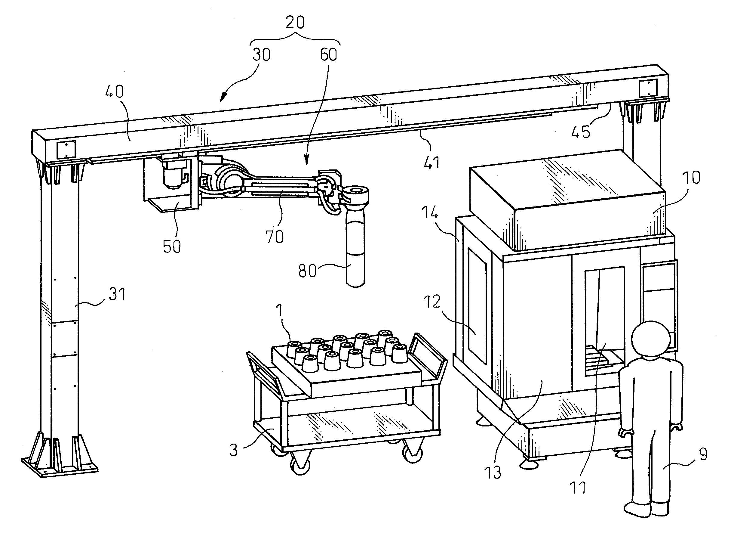
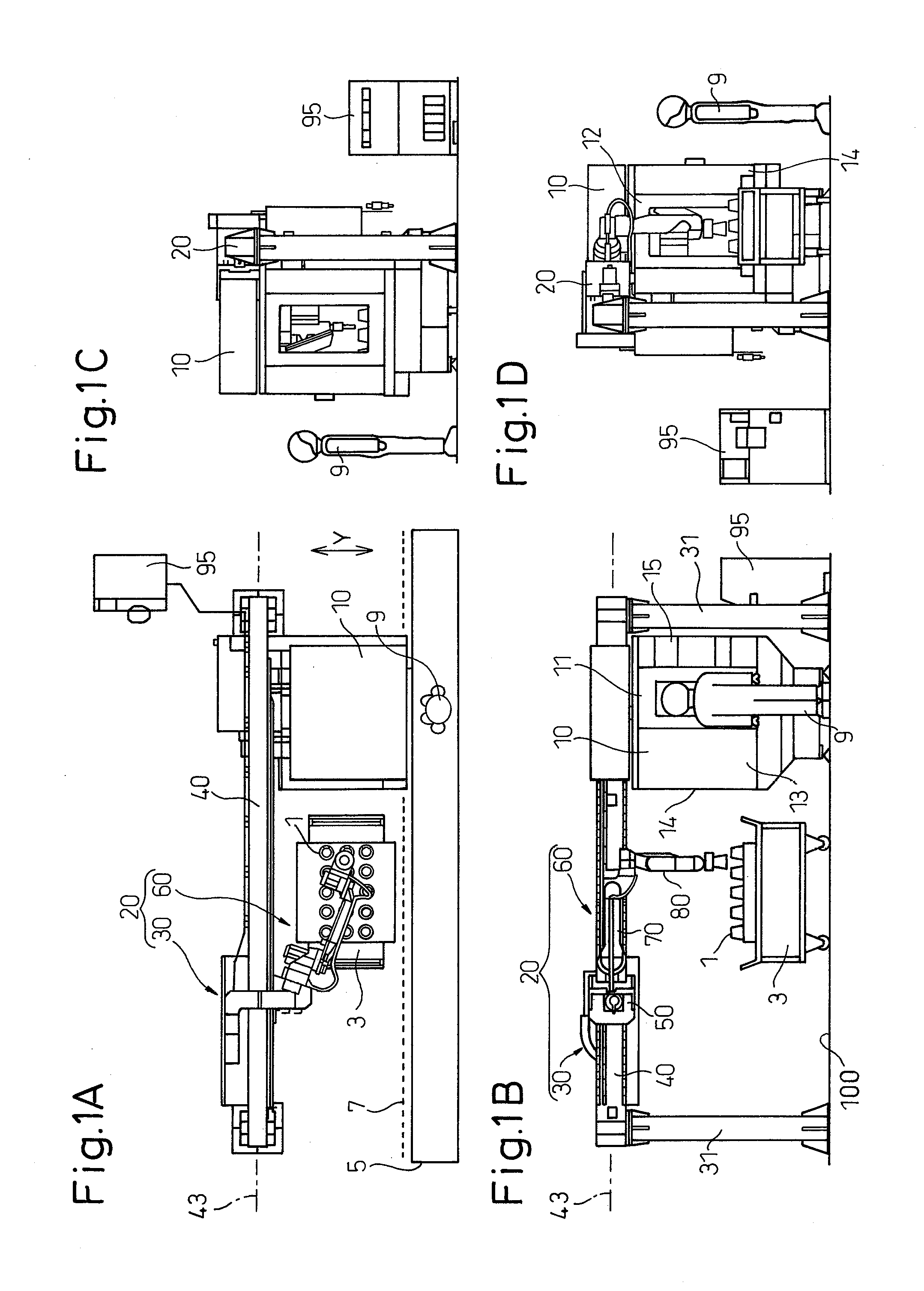
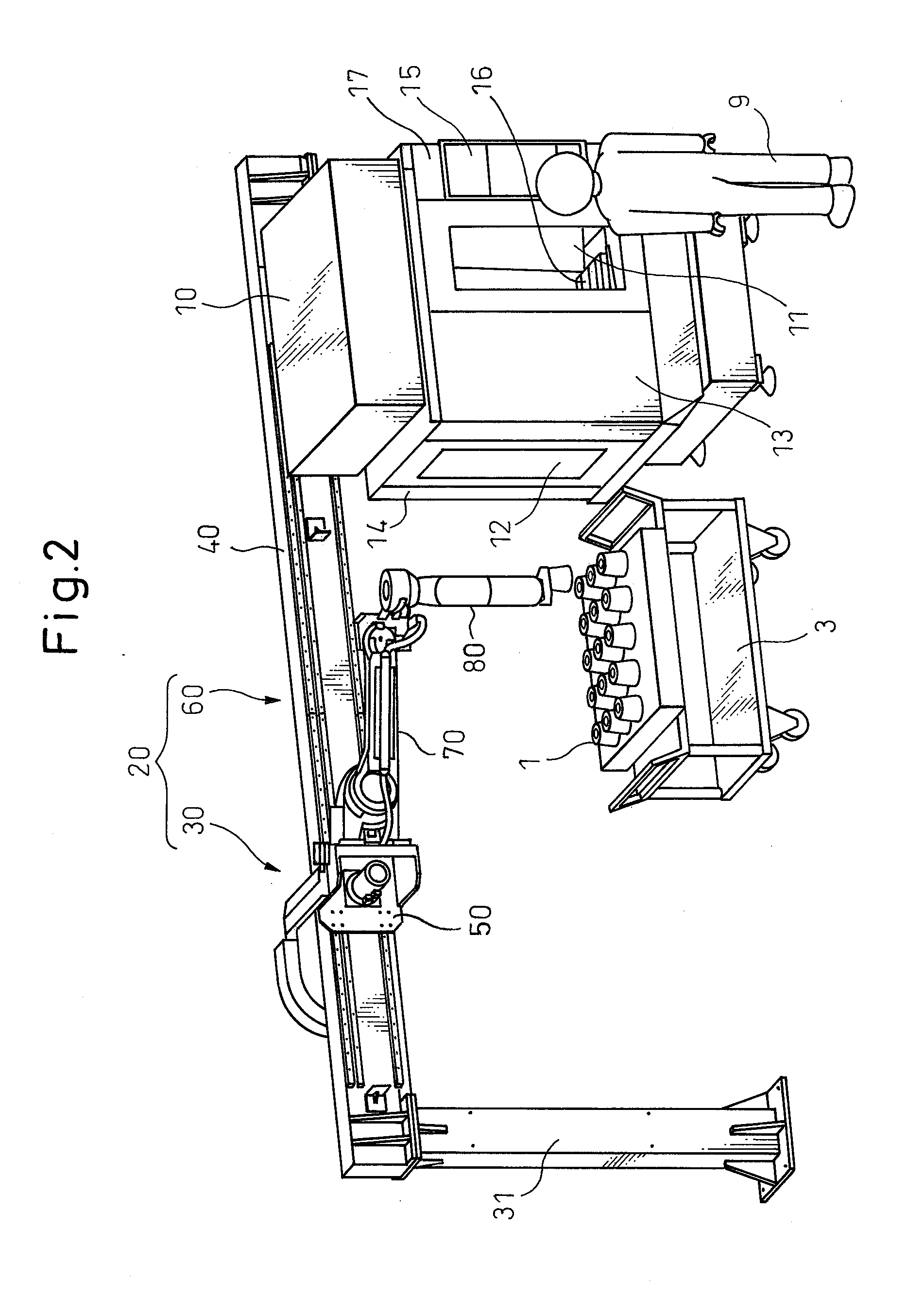
[0032]Referring to the drawings, FIGS. 1A-1D and 2 schematically illustrate an overall configuration of a workpiece transfer robot system according to one embodiment of the present invention. FIG. 1A is a plan view, FIG. 1B is a front view, FIG. 1C is a right side view, FIG. 1D is a left side view, and FIG. 2 is a perspective view.

[0033]The workpiece transfer robot system according to the illustrated embodiment (hereinafter referred simply to as a robot system) is configured to include a single robot 20 for transferring a workpiece relative to a single machine tool 10. The robot 20 includes a traveling axis mechanism 30 including a track member 40 defining a traveling axis 43 and a slider 50 attached to the track member 40 and capable of sliding and traveling along the travelin...


PUM


Abstract

A workpiece transfer robot system including a machine tool provided with a workpiece support section and a robot capable of transferring a workpiece relative to the workpiece support section of the machine tool. The machine tool includes a cover surrounding at least the workpiece support section. The cover includes a first side wall provided with a first opening usable for a workpiece transferring task of the robot. The robot includes a track member defining a traveling axis extending in a direction perpendicular to the first side wall of the cover of the machine tool; a slider attached to the track member and capable of traveling along the traveling axis; a first arm attached to the slider and capable of swinging about a first swing axis; a second arm attached to the first arm and capable of swinging about a second swing axis parallel to the first swing axis; and a workpiece hold section provided on the second arm and capable of accessing the workpiece support section through the first opening of the cover of the machine tool.

Description

BACKGROUND OF THE INVENTION[0001]1. Field of the Invention[0002]The present invention relates to a workpiece transfer robot system in which a robot transfers a workpiece relative to a machine tool.[0003]2. Description of the Related Art[0004]A robot system for transferring, in particular, loading or unloading, a workpiece relative to a machine tool, which includes a robot composed of a traveling axis mechanism including a track member defining a traveling axis and a slider traveling along the track member, and a movable arm mechanism (i.e., a robot arm) mounted on the slider, is known. In a production line equipped with a robot, a workpiece is transferred to several locations, such as a workpiece support section inside a machine tool, a feed table on which a workpiece before being loaded into the machine tool is placed, a delivery table on which a workpiece unloaded from a machine tool after being processed by the machine tool is placed, etc. Thus, the robot composed of a traveling ...

Claims


Application Information

Patent Timeline
Patent Type & Authority Applications(United States)
IPC IPC(8): B66C23/00
CPCB23Q7/005B23Q7/04B25J9/046B25J5/02B23Q11/08
Inventor ODA, MASARUSHIRAHATA, TORUINOUE, TOSHIHIKOIWAYAMA, TAKATOSHIUEMATSU, MASAAKIOOTANI, KENTAROU
Owner FANUC LTD
Why Eureka
Try Eureka