Refrigerant compressor

a refrigeration compressor and compressor technology, applied in the direction of pumps, mechanical equipment, liquid fuel engines, etc., can solve the problems of certain wear and other problems, and achieve the effect of simplifying assembly and stock handling

Inactive Publication Date: 2010-04-15
DANFOSS AS
View PDF3 Cites 4 Cited by
  • Summary
  • Abstract
  • Description
  • Claims
  • Application Information

AI Technical Summary

Benefits of technology

[0017]Preferably, all connecting rods have the same embodiment. This simplifies the assembly and the stock handli...

Problems solved by technology

With such an arrangement of the connecting rods, it may be observed during operation th...

Method used


Image

  • Refrigerant compressor
  • Refrigerant compressor
  • Refrigerant compressor

Examples


Embodiment Construction

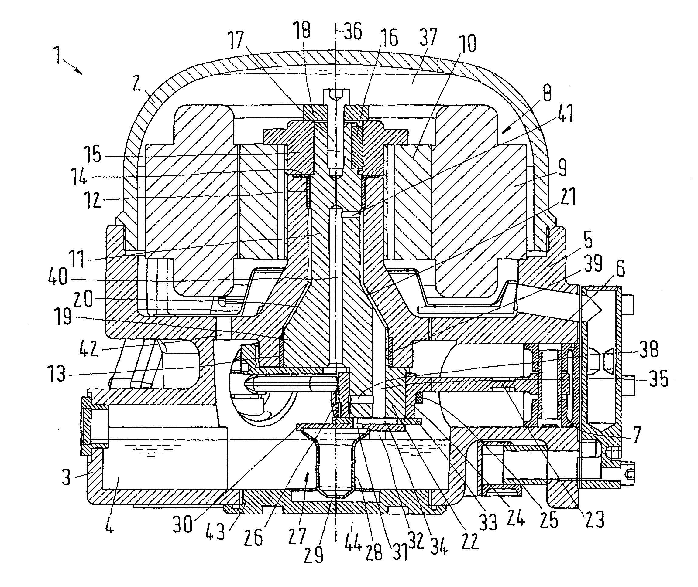
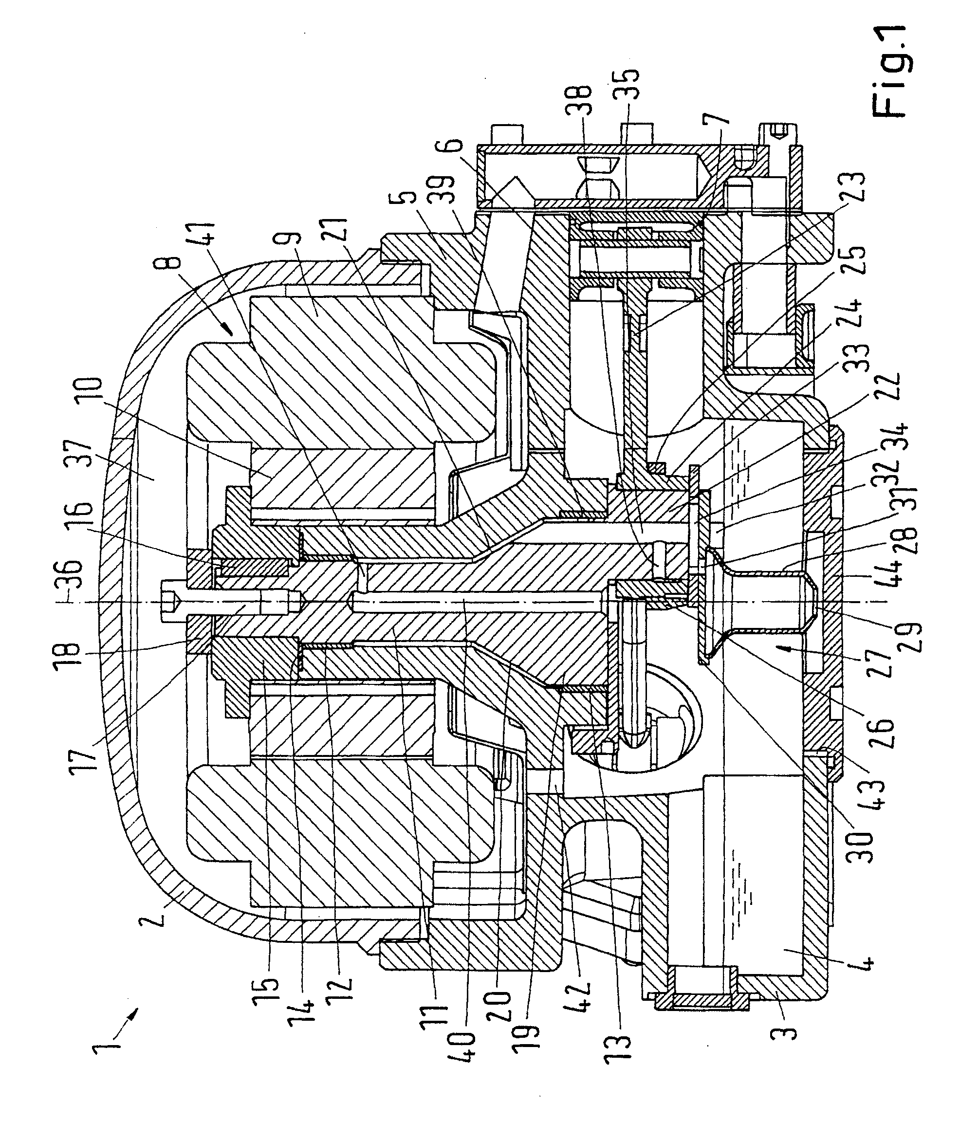
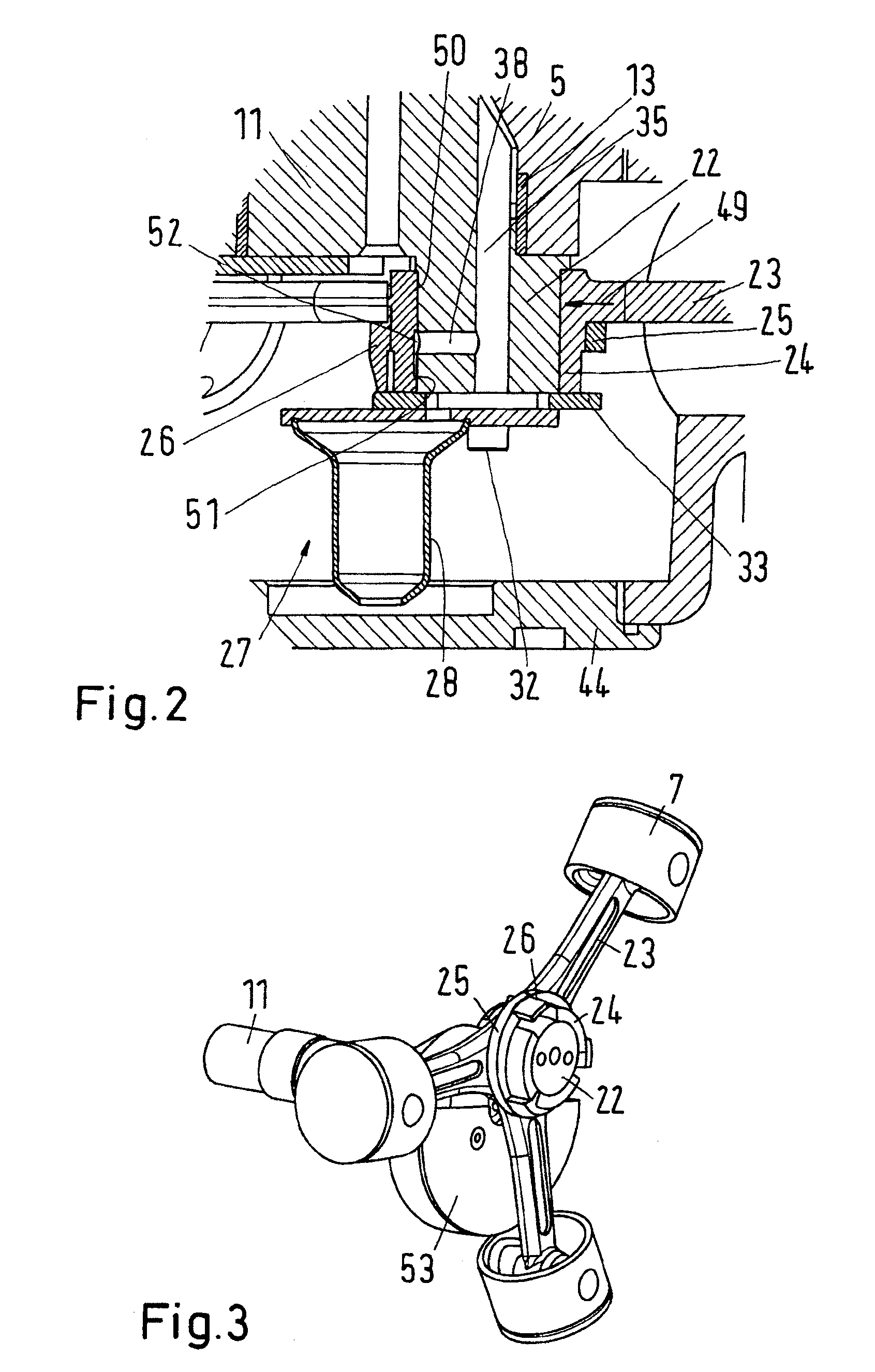
[0022]FIG. 1 shows a semi-hermetic refrigerant compressor 1 with a housing 2, whose bottom part 3 comprises an oil sump 4. The compressor 1 has a compressor block 5, in which several, in the present case three cylinders 6 are arranged in a star shape and symmetrically, that is, in the circumferential direction the central axes of the cylinders 6 have a distance of 120°. A piston 7 is arranged in each cylinder 6.

[0023]It is shown that the bottom part 3 of the housing 2 is made in one piece with the compressor block 5. This is advantageous, but not absolutely necessary. The bottom part 3 and the compressor block 5 can also be subdivided. Compressor block 5 and bottom part 3 can be made as castings.

[0024]Further, the compressor 1 has an electric motor 8, whose stator 9 is connected to the compressor block 5 in a manner not shown in detail. Further, the motor 8 has a rotor 10. The motor 8 can be made as a permanent-magnet activated synchronous motor, whose rotor can comprise permanent m...


PUM


Abstract

The invention concerns a refrigerant compressor (1), in particular a semi-hermetic refrigerant compressor, with a compressor block (5) comprising several cylinders arranged in a star shape, a motor, whose rotor is unrotatably connected to a crankshaft (11) that comprises a crank pin (22) and is supported in a bearing (13) in the compressor block (5), and a piston in each cylinder, each piston being connected via a connecting rod (23) to the crank pin (22), the connecting rod (23) comprising a bearing pad (24) that rests on the crank pin (22), the bearing pads (24) of all connecting rods (23) being held on the crank pin (22) by means of a ring arrangement (25). It is endeavoured to keep the load on the crankshaft small. For this purpose, each connecting rod (23) has a power application point (49) at the crank pin (22), which is displaced in the direction of the bearing (13) in relation to the axial centre of the crank pin (22).

Description

CROSS REFERENCE TO RELATED APPLICATION[0001]Applicant hereby claims foreign priority benefits under U.S.C. §119 from German Patent Application No. 10 2008 025 323.5 filed on May 27, 2008, the contents of which are incorporated by reference herein.FIELD OF THE INVENTION[0002]The invention concerns a refrigerant compressor, in particular a semi-hermetic refrigerant compressor, with a compressor block comprising several cylinders arranged in a star shape, a motor, whose rotor is unrotatably connected to a crankshaft that comprises a crank pin and is supported in a bearing in the compressor block, and a piston in each cylinder, each piston being connected via a connecting rod to the crank pin, the connecting rod comprising a bearing pad that rests on the crank pin, the bearing pads of all connecting rods being held on the crank pin by means of a ring arrangement.BACKGROUND OF THE INVENTION[0003]Such a refrigerant compressor is, for example, known from DD 64 769 A. This refrigerant compr...

Claims


Application Information

Patent Timeline
IPC IPC(8): F04B27/04
CPCF04B27/0414Y10S417/902F04B53/147F04B53/144
Inventor SUSS, JURGENJEPSEN, CHRISTIAN
Owner DANFOSS AS
Why Eureka
Try Eureka