Determination and use of power system sensitivities

Active Publication Date: 2010-04-15
HITACHI ENERGY SWITZERLAND AG
View PDF3 Cites 41 Cited by
  • Summary
  • Abstract
  • Description
  • Claims
  • Application Information

AI Technical Summary

Benefits of technology

[0014]Exemplary embodiments disclosed herein can enable an improved, fast and reliable power flow control in power sy

Problems solved by technology

As a consequence of the competition between utilities and the emerging need to optimize assets, substantially increased amounts of power are transmitted through the existing networks, occasionally causing congestion, transmission bottlenecks and/or oscillations of parts of the power transmission systems.
Thus in the time period prior to a disturbance the network is operated less efficiently due to the security constraint.
Furthermore, in the event of more severe disturbances, i.e. disturbances not included in the security constraint, the response is slow since there is an operator in the loop and the state snapshots, which often are obtained through a SCADA system and state estimation, may not be updated reliably or rapidly enough to make

Method used


Image

  • Determination and use of power system sensitivities
  • Determination and use of power system sensitivities
  • Determination and use of power system sensitivities

Examples


Embodiment Construction

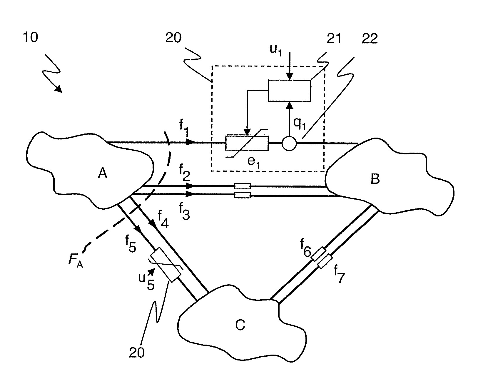
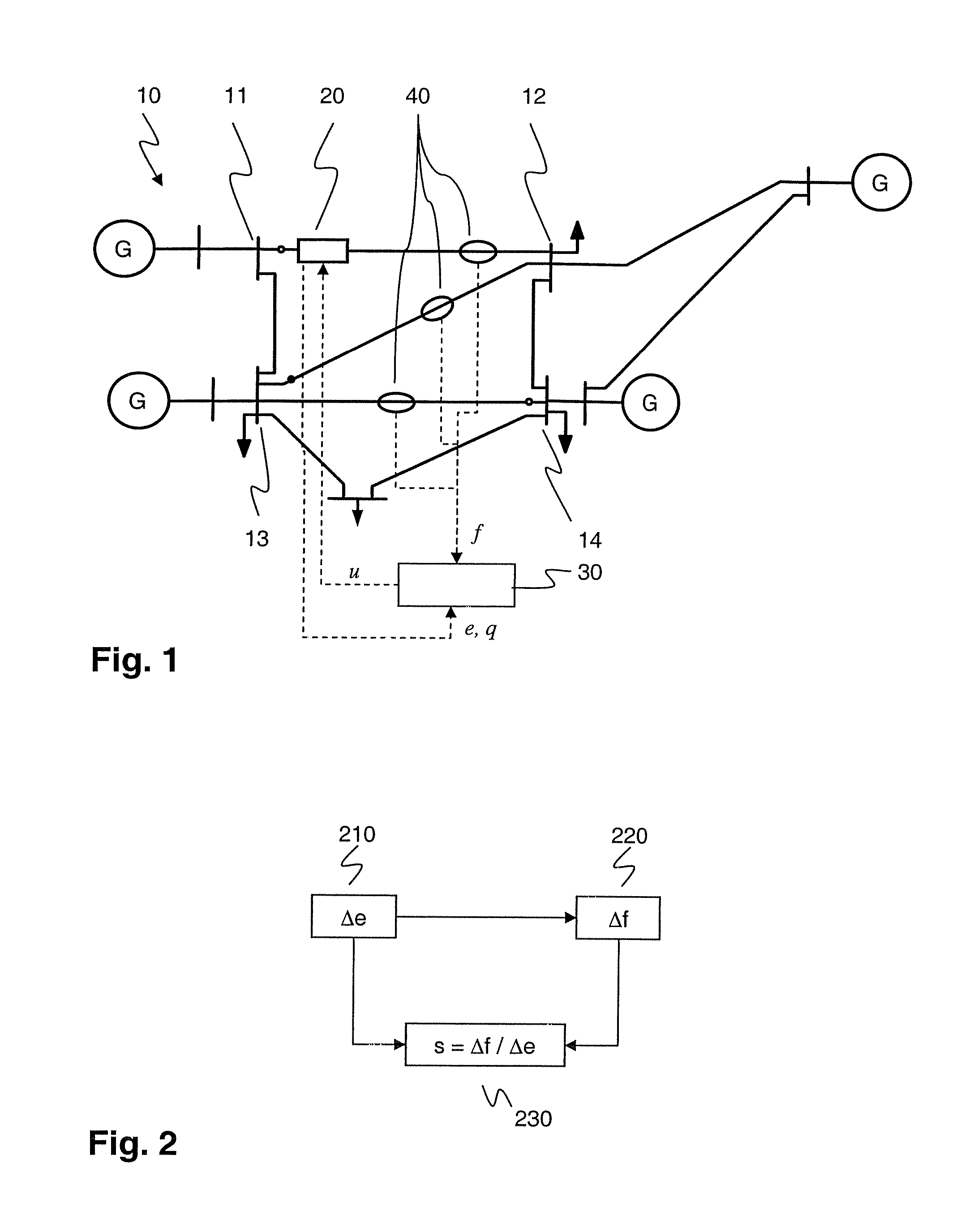
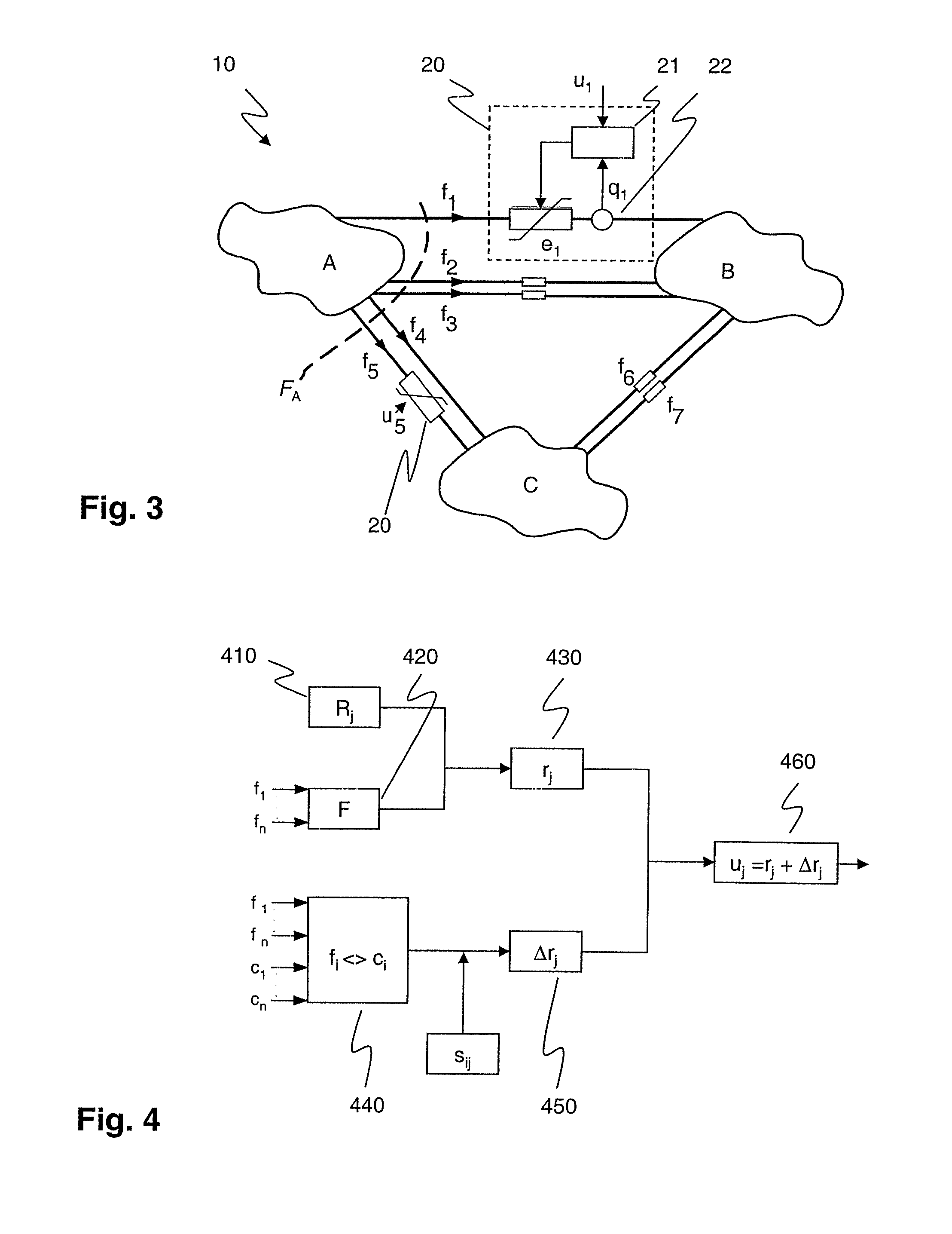
[0022]According to the disclosure, power system sensitivities or normalized power flow responses relate a power flow response of a particular flow path to a control parameter of a Power Flow Control Device (PFC) in a different flow path. To this end, variations in a control parameter and variations in a power flow response responsive to the variation in said control parameter are determined in a way sufficiently synchronized and / or correlated to allow establishing an unambiguous causal relationship in the form of a power system sensitivity. Power system sensitivities may be updated in real time with limited computational effort, and may subsequently be used for controlling or redistributing power flow in a meshed power network with at least two parallel power flow or transfer paths.

[0023]The power flow response may be an actual active or apparent power flow or a current measured by a suitable power flow response measuring unit or sensor. However, according to a first exemplary embod...


PUM


Abstract

The present disclosure relates to power system sensitivities as computed from power flow parameters and control parameters of a Power Flow Control Device (PFC). To this end, control parameter variations are applied to or generated by a PFC, and comprise variations in a control input u, a control effort e (injected series voltage, inserted series reactance), or a control effect q (power flow, active power transfer, phase-shift, current). A power flow response measuring unit measures a variation of a power flow response such as current, active or apparent power, in a way sufficiently synchronized with the control parameter variation to allow establishing an unambiguous causal relationship or correspondence in the form of a power system sensitivity. The latter may be on-line adapted to continuously reflect an updated aspect of the power system behaviour, and thus enable an improved, fast and reliable power flow control in power systems comprising a meshed power network with two parallel flow paths or corridors connecting two areas or sub-systems.

Description

RELATED APPLICATIONS[0001]This application claims priority under 35 U.S.C. §119 to EP Application 06405422.4 filed in Europe on Oct. 5, 2006, and as a continuation application under 35 U.S.C. §120 to PCT / EP2007 / 060412 filed as an International Application on Oct. 2, 2007 designating the U.S., the entire contents of which are hereby incorporated by reference in their entireties.TECHNICAL FIELD[0002]The disclosure relates to the field of power flow control in electric power systems comprising a plurality of power transmission corridors interconnecting distinct areas.BACKGROUND INFORMATION[0003]In the wake of the ongoing deregulations of the electric power markets, load transmission and wheeling of power from distant generators to local consumers has become common practice. As a consequence of the competition between utilities and the emerging need to optimize assets, substantially increased amounts of power are transmitted through the existing networks, occasionally causing congestion...

Claims


Application Information

Patent Timeline
IPC IPC(8): G06F19/00
CPCH02J3/005Y04S10/265Y02E60/728H02J3/24Y02E60/00Y04S10/00Y04S10/22Y02E40/70H02J3/242H02J3/007
Inventor BERGGREN, BERTILLARSSON, MATSBENGTSSON, TORDKORBA, PETROUDALOV, ALEXANDRE
Owner HITACHI ENERGY SWITZERLAND AG
Why Eureka
Try Eureka