Harness connection member

Inactive Publication Date: 2010-04-22
FURUKAWA AUTOMOTIVE SYST +1
View PDF3 Cites 13 Cited by
  • Summary
  • Abstract
  • Description
  • Claims
  • Application Information

AI Technical Summary

Benefits of technology

[0009]In order to prevent the above mentioned damage of the connection members, it has been also proposed to wind an insulating tape around the branch connection members. However, this taping operation apparently increases the number of manufacturing steps.
[0010]The present invention has for its object to provide a novel ha

Problems solved by technology

In the splice joint method, electric wires have to be connected to the main electric wire in such a manner that a group of one to three branch wires is connected by clamping, and therefore after connecting the branch wires, the harness is difficult to be handled.
Moreover, the joint work could not be carried out on a manufacturing line, and therefore the splice joint method is not suitably applied to the line production.
However, the number of parts such as connectors, cooperating conventional connectors, bus bars, connection terminals an

Method used


Image

  • Harness connection member
  • Harness connection member
  • Harness connection member

Examples


Example

Embodiment 1

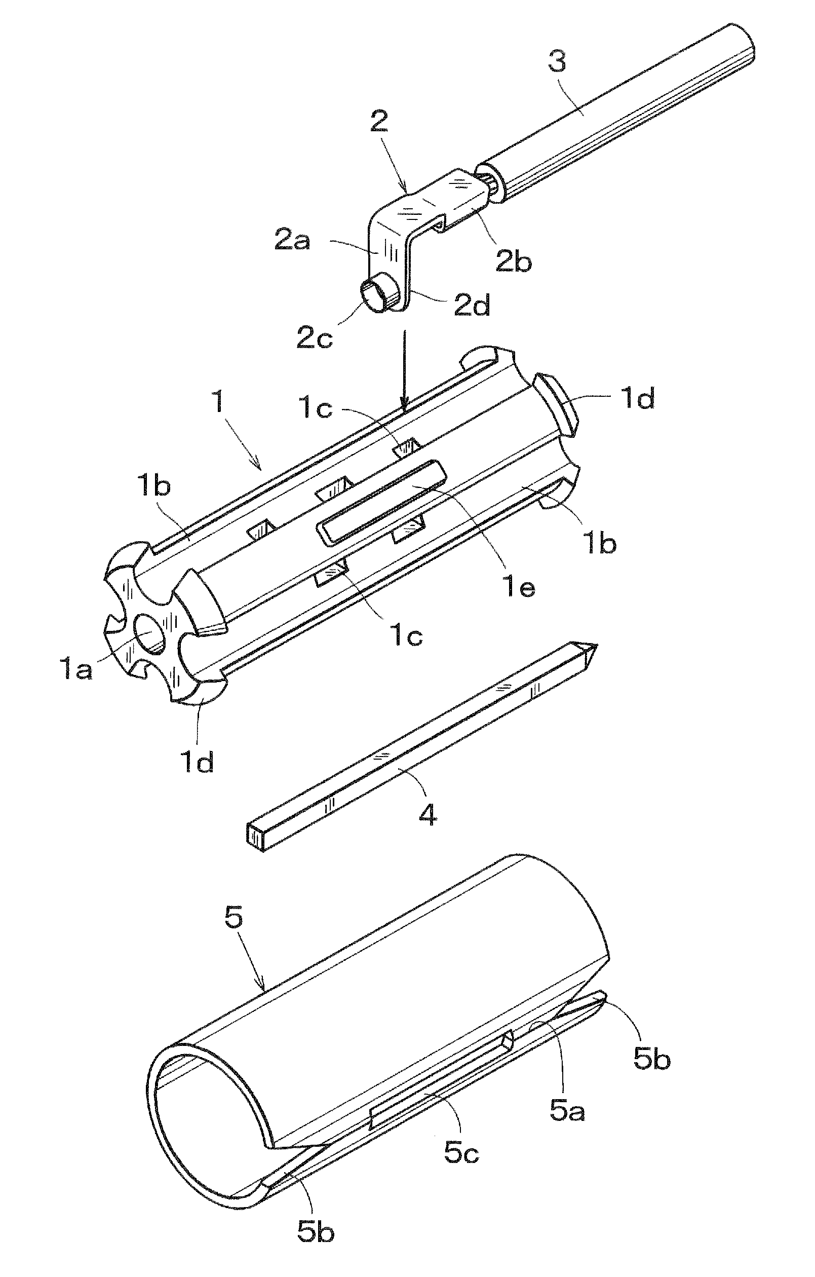
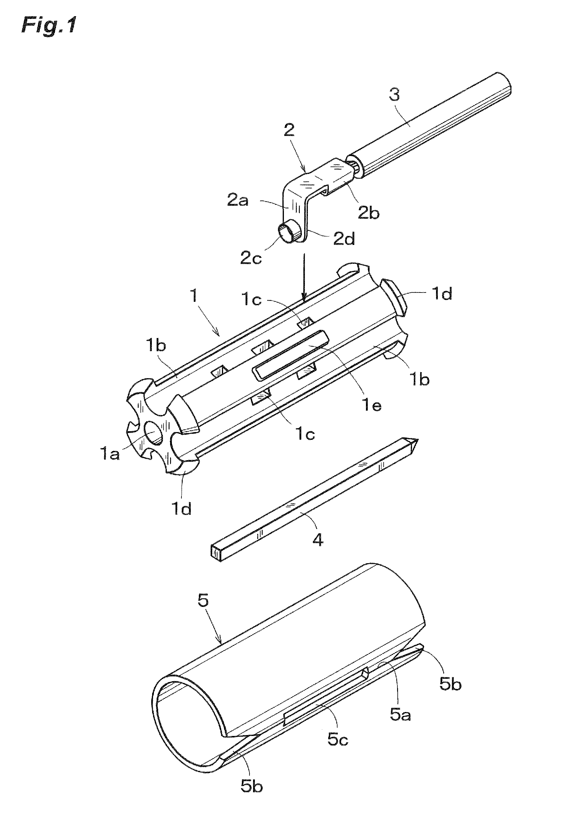
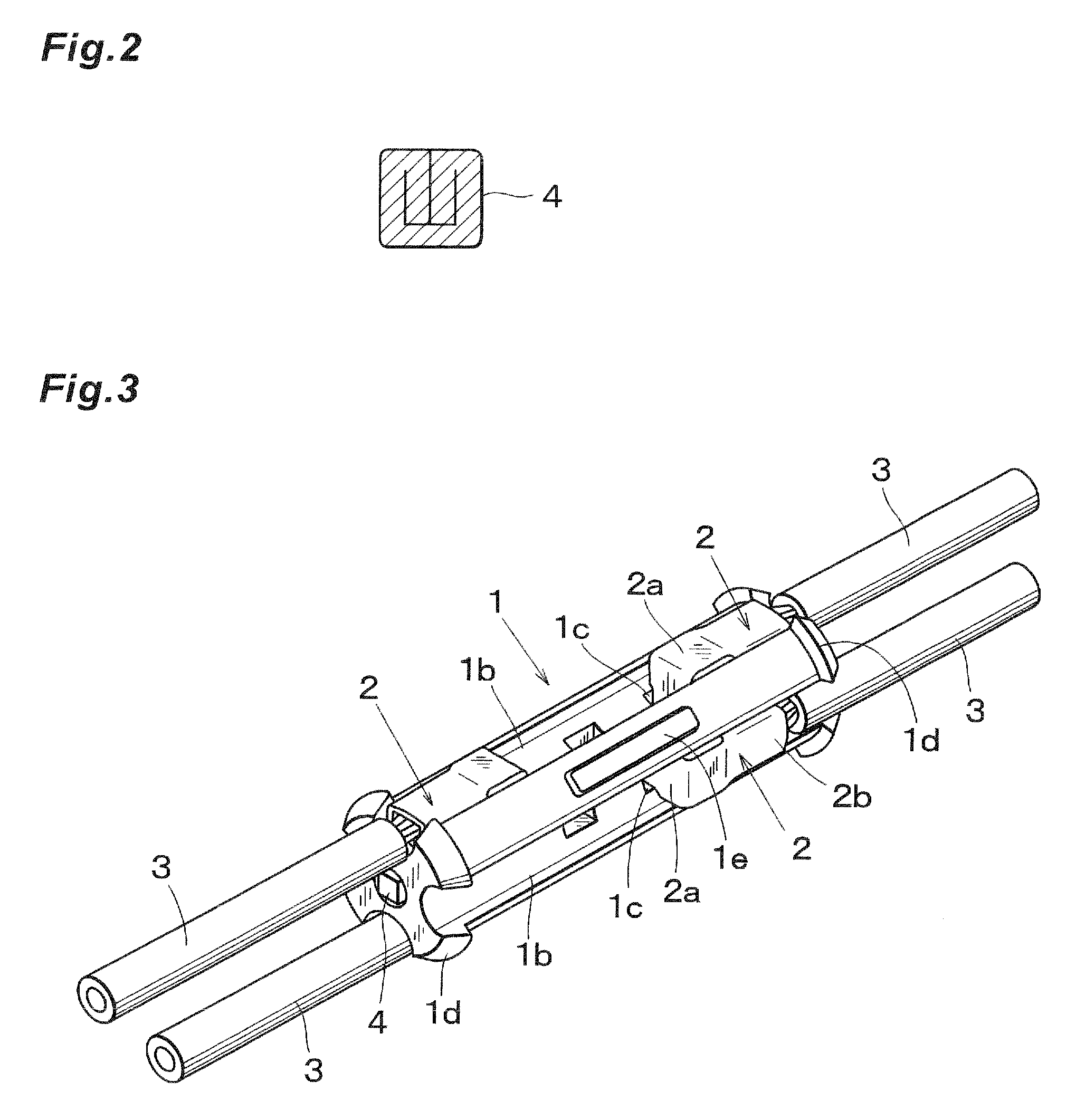
[0037]As shown in FIG. 1 the harness connection member of the embodiment 1 is mainly consisting of a holder 1 having a pin terminal insertion hole 1a, elongated grooves 1b and electric terminal insertion holes 1c; a plurality of electric terminals 2 each having a connecting portion 2a to be inserted into the electric terminal insertion hole 1c of the holder 1 and a clamping portion 2b at which a core conductor of an electrical wire 3 is clamped; a pin terminal 4 for mutually connecting a plurality of electric terminals 2; and a cover member 5 for covering the outer surface of the holder 1.

[0038]The holder 1 is formed by a substantially cylindrical body made of a synthetic resin and the pin terminal insertion hole 1a is formed along a central axis of the holder 1 and four elongated grooves 1b each having a semicircular cross sectional shape are formed in an outer surface of the holder 1 such that the elongated grooves 1b extend in an longitudinal direction. In a bottom su...

Example

[0051]In the second embodiment 2, in order to simplify the internal structure, the holder is formed by two holder halves 1, 1′ as illustrated in FIG. 8. In FIG. 1, portions similar to those shown in FIG. 1 are denoted by the same reference numerals used in FIG. 1.

[0052]When the internal structure of the holder 1, 1′ is simplified, the injection molding can be performed easily. The holder halves 1, 1′ having the identical structure are obtained by dividing the holder 1 of the first embodiment in the longitudinal direction. In each of the holder halves 1, 1′, there are formed a dovetail projection 1f and a cooperating dovetail groove 1g, and the holder halves 1, 1′ can be firmly assembled by relatively sliding the holder halves 1, 1′. The assembled holder halves 1, 1′ constitute the holder having a substantially cylindrical shape similar to the holder 1 shown in FIG. 1. The pin terminal insertion hole 1a is formed to insert the pin terminal 4 along the center axis of the assembled hol...


PUM


Abstract

A harness connection member has a cover member. In fitting a cover member to a holder, a split slit is opened with use of a slit, and wires are inserted into the holder. Thereafter, the cover member is moved to the holder, then moved over one projected annular part of the holder, and fitted into the projected ring parts. A concaved strip part is fitted to a convexed strip part to complete the installation, whereby the cover member cannot be moved relative to the holder in both longitudinal and circumferential directions.

Description

FIELD OF THE INVENTION [0001]The present invention relates to a harness connection member for use in harness circuits provided in, for instance automobiles.BACKGROUND OF THE INVENTION[0002]In a harness circuit, it is often required to provide one or more branch electric wires from a main electric wire. Heretofore, there have been widely proposed two joint methods, i.e. a splice joint method in which a part of an electrically insulating sheath of the main electric wire is removed and one or more branch electric wires are connected by clamping them to an exposed core conductor of the main electric wire, and a joint connector method in which a circuit branch connector is arranged at a terminal of the main electric wire and conventional connectors having clamp terminals connected to the main wire and branch wires are inserted into the circuit branch connecter to constitute the branch circuit. The later method is disclosed in a Japanese Patent Document 1 mentioned later.[0003]In the spli...

Claims


Application Information

Patent Timeline
IPC IPC(8): H01R4/70H02G3/04
CPCB60R16/0215H01R4/70H01R9/11H01R31/08H01R13/639H02G15/18H01R13/506B60R16/02H02G15/02
Inventor AMBO, TSUGIOTANAKA, YOSHIKAZUMATSUMOTO, TOMOKAZUFUJIWARA, SATORU
Owner FURUKAWA AUTOMOTIVE SYST
Why Eureka
Try Eureka