Double path torsional damper

a torsional damper and double-path technology, applied in the direction of fluid gearings, machine supports, couplings, etc., can solve the problems of increased unwanted vibration, increased wear on the components of the drivetrain as well as passenger discomfort, and substantial inertia of the floating flange(s), so as to reduce the transmission of engine vibration

Active Publication Date: 2010-04-22
SCHAEFFLER TECH AG & CO KG
View PDF8 Cites 32 Cited by
  • Summary
  • Abstract
  • Description
  • Claims
  • Application Information

AI Technical Summary

Benefits of technology

[0008]One object of the invention is to provide a device for reducing the

Problems solved by technology

During clutch engagement, the engine vibration will be transferred via the clutch to the drivetrain which causes excess wear on components of the drivetrain as well as passenger discomfort.
However, they all can introduce extra undesirable resonant frequencies that cause or increase unwanted vibrations.
Unfortunately, the inertia of floating flange(s) is substantial for any concentric spring series arrangement.
This inertia introduces an addition degree

Method used


Image

  • Double path torsional damper
  • Double path torsional damper
  • Double path torsional damper

Examples


example

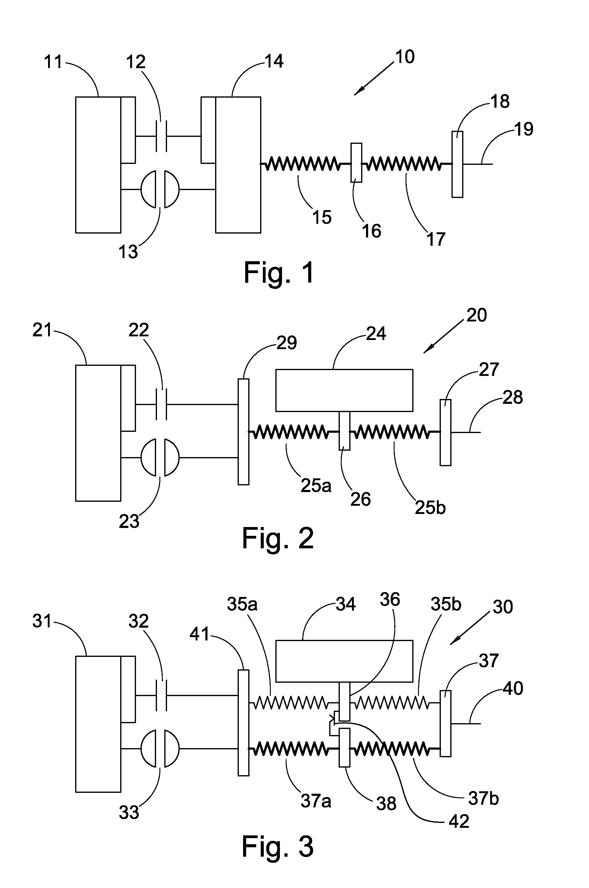
[0033]For an engine with a deactivation system (V4-V8—four cylinders are shut down when idling) a series damper with characteristic like FIG. 6 is needed. FIG. 6 graphically portrays the damper characteristic for the V / 4-V / 8 engine. During the V4 mode, the engine is running in the first stage and during the V8 mode the engine runs in the second stage. For a conventional series damper (FIG. 1) we need a spring rate of 18.25 Nm / ° for the first stage and 53.69 Nm / ° for the second stage. The only results shown are for the V4 mode, which is the worst case, in which Turbine Inertia=0.03 kgm2 / rad, Floating flange Inertia=0.0135 kgm2 / rad, and Isolator Hub Inertia=0.002 kgm2 / rad.

[0034]The simulation results for two conventional dampers are shown in FIG. 8. Series Double Damper 20 has a damper mode at about 1500 rpm and Series Turbine Damper 10 has an inner flange mode at about 2500 rpm. In V8 mode the turbine mode in SDD 20 is about 750 rpm and inner flange mode in STD 10 is about 1250 rpm. ...


PUM


Abstract

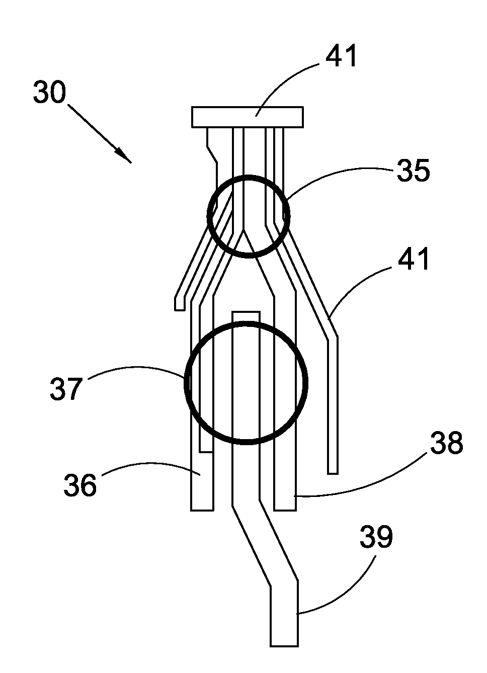
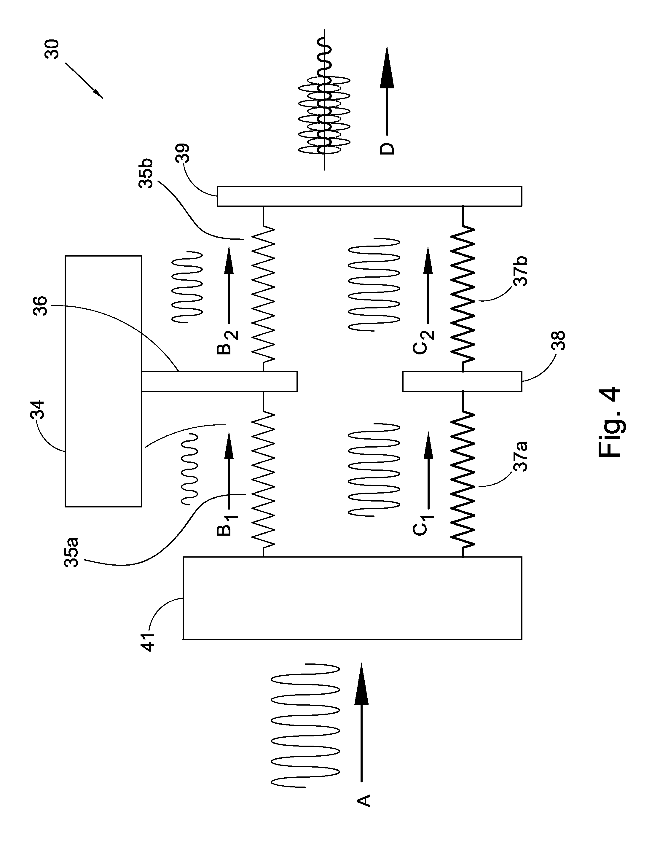
The present invention is a double path torsion isolator for use in conjunction with a torque converter. Each of the two vibration paths includes a flange with a spring connection to each of the torque converter cover and an output connection attached to the transmission shaft. The torque converter turbine is connected to one of the flanges to provide a different frequency to the associated vibration path. When the lockup clutch is engaged, the engine vibration is divided along the two vibration paths toward the common output connection. The vibration frequency of the paths are adjusted so that the frequencies of the two paths are 180° out of phase at the output connection providing a vibration cancellation effect to the output connection.

Description

CROSS-REFERENCE TO RELATED APPLICATIONS[0001]This application claims the benefit under 35 U.S.C. §119(e) of U.S. Provisional Application No. 61 / 196,541 filed Oct. 17, 2008 which application is incorporated herein by reference.FIELD OF THE INVENTION[0002]The present invention relates to the field of vehicle drive trains. More specifically, the invention relates to reduction of the conduction of engine vibration to the vehicle transmission and more particularly to the dampening of engine vibration through the torque converter.BACKGROUND OF THE INVENTION[0003]Clutches are used to provide a mechanical by-pass for the hydrodynamic coupling in torque converters in order to improve fuel economy in vehicles. The clutch is engaged and stays locked as soon as torque multiplication is no longer required. During clutch engagement, the engine vibration will be transferred via the clutch to the drivetrain which causes excess wear on components of the drivetrain as well as passenger discomfort. To...

Claims


Application Information

Patent Timeline
IPC IPC(8): F16F13/00
CPCF16H2045/0231F16F15/13484
Inventor FARAHATI, RASHIDSWANK, MICHAEL G.
Owner SCHAEFFLER TECH AG & CO KG
Why Eureka
Try Eureka