Omni-directional drive device and omni-directional vehicle using the same

a drive device and omni-directional technology, applied in the direction of spoked wheels, bicycles, transportation and packaging, etc., can solve the problems of high complexity of the arrangement of supplying electric power to the electric motor from a power source located externally of the driven wheel, high difficulty in compact design of the device, and high difficulty in service and maintenance. , to achieve the effect of reducing the mass of moving parts, enhancing freedom in compact design, and high durability

Active Publication Date: 2010-04-22
HONDA MOTOR CO LTD
View PDF25 Cites 84 Cited by
  • Summary
  • Abstract
  • Description
  • Claims
  • Application Information

AI Technical Summary

Benefits of technology

[0010]According to the omni-directional drive device of the present invention, when the two rotary members (drive force transmitting members) disposed laterally one next to the other are rotated in a same direction at a same speed by using the corresponding drive units, the main wheel is rotatively actuated (around the symmetric axis=central axial line B) in the same direction as the two rotary members via the free rollers (drive force transmitting members), and this applies a fore-and-aft traction to the ground contact surface of the main wheel. When the two rotary members are rotatively actuated in different directions and/or at different speeds by using the drive units, because the free rollers engage the main wheel with the central axial line of each free roller slanted with respect to the central axial line B of the main wheel, a component of force that depends on this slanting angle acts upon the outer surface of the main wheel so that the main wheel turns around the center of the circular cross section (around the cross sectional center=central axial line C), and this applies a lateral traction to the ground contact surface of the main wheel. Therefore, by individually controlling the rotational directions and rotational speeds of the two rotary members by using the corresponding drive units, a traction force of any desired direction can be produced as a combination of the vectors of the fore-and-aft and lateral tractions.
[0011]Because the drive units for individually actuating the rotary members are all provided on the side of the base, the arrangement for supplying power such as electricity to the drive units is not required to be complex. This in turn allows high durability, ease of maintenance, minimization of the mass of moving parts and enhanced freed...

Problems solved by technology

Therefore, the arrangement for supplying electric power to the electric motor from a power source located externally of the driven wheel is inevitably highly complex, and difficult to service and maintain.
If the power source is incorporated in the driven...

Method used


Image

  • Omni-directional drive device and omni-directional vehicle using the same
  • Omni-directional drive device and omni-directional vehicle using the same
  • Omni-directional drive device and omni-directional vehicle using the same

Examples


Embodiment Construction

)

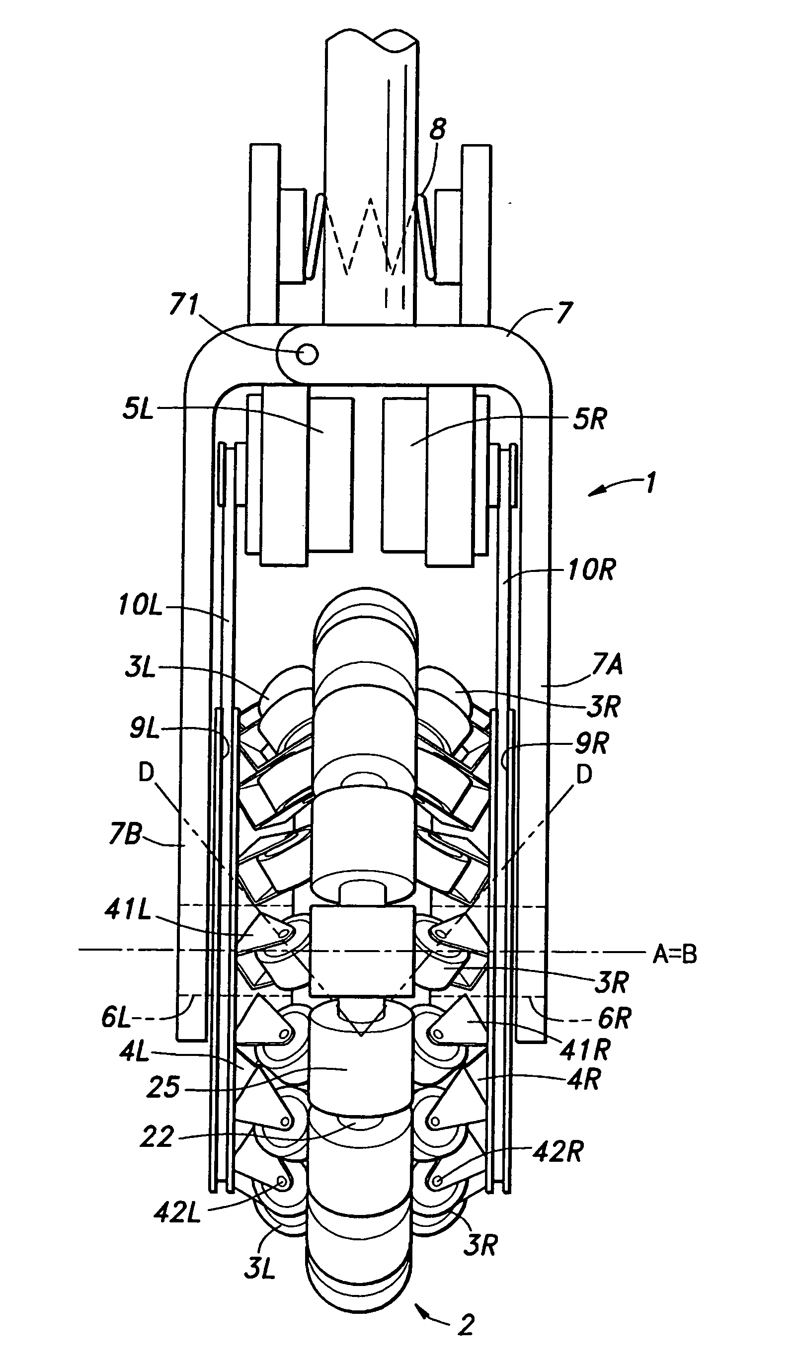
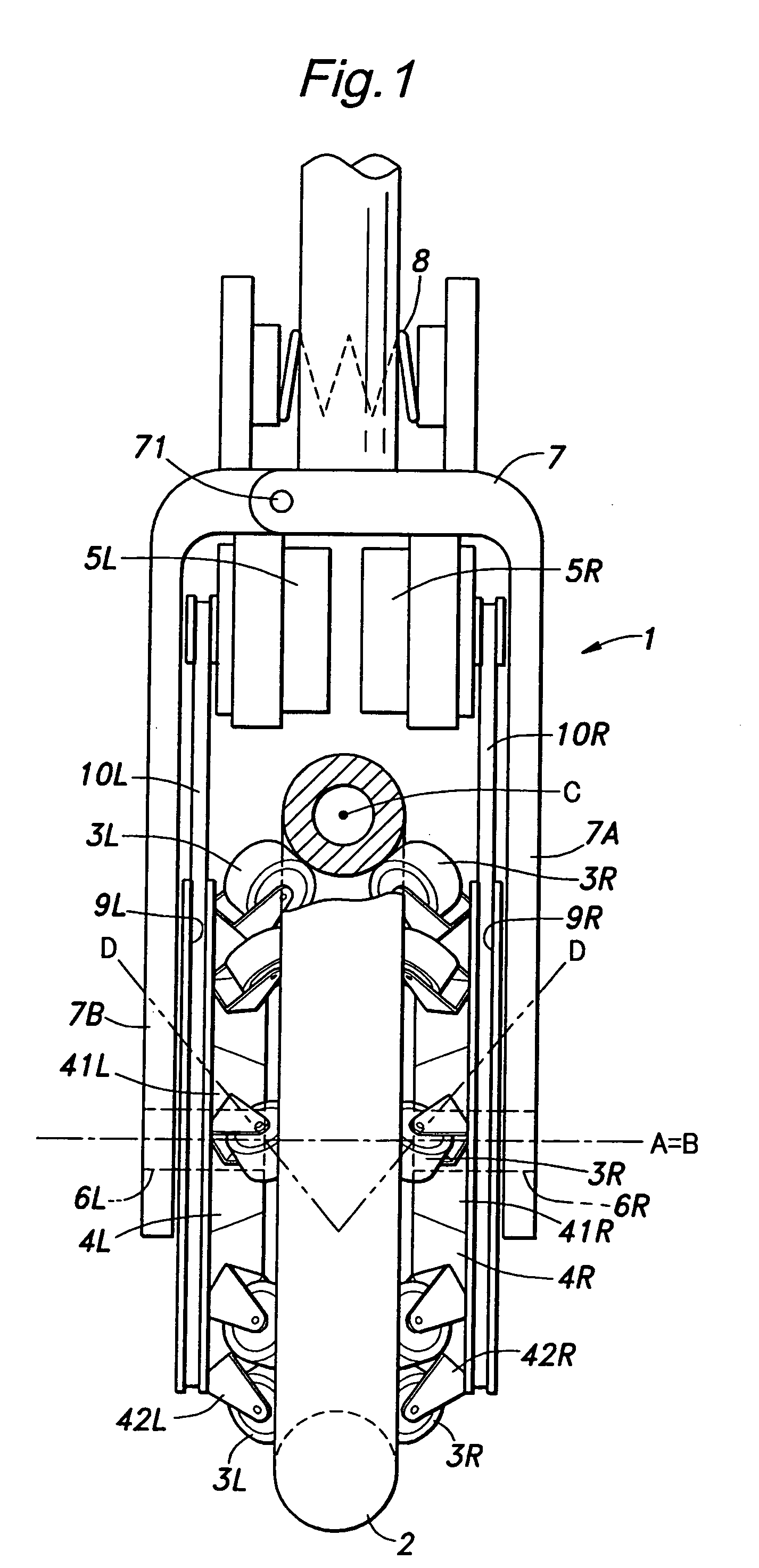
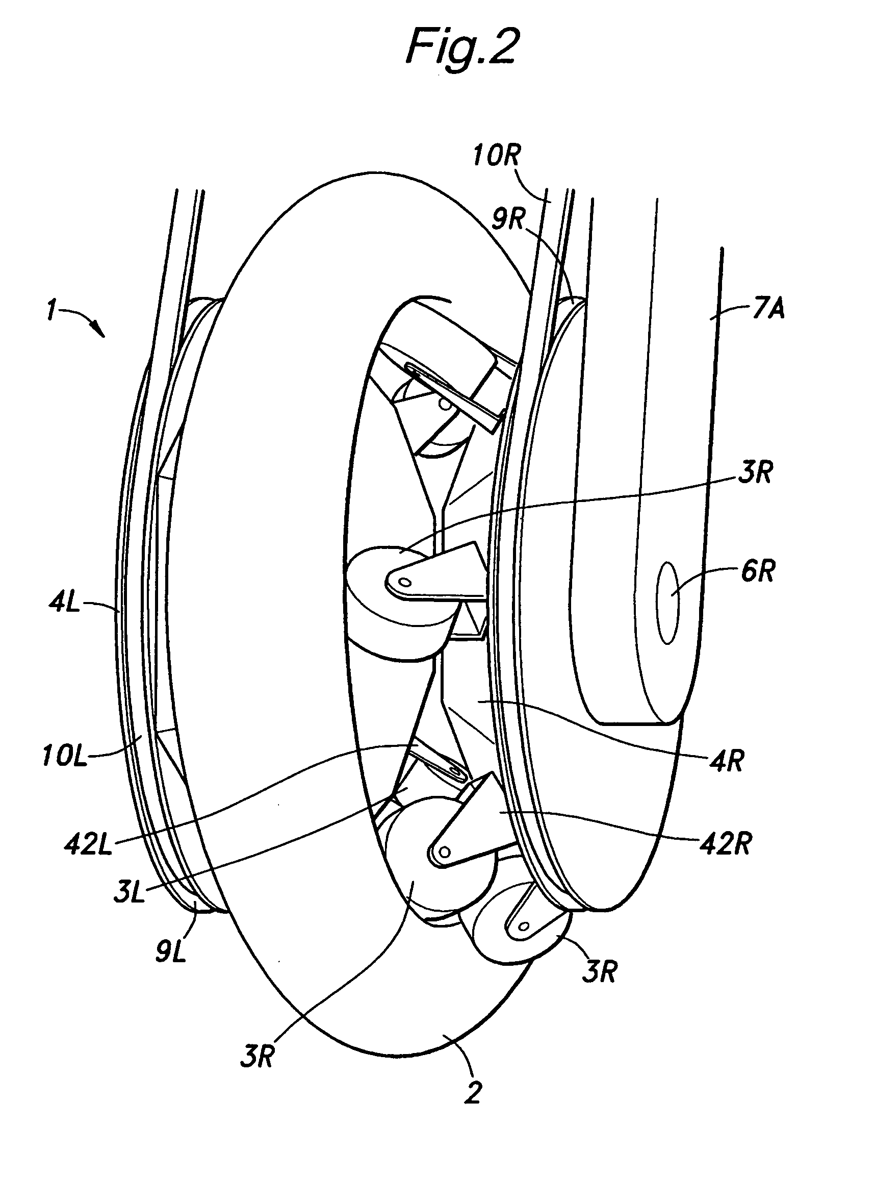
[0015]An omni-directional drive device embodying the present invention is described in the following with reference to FIGS. 1 to 5.

[0016]The illustrated omni-directional drive device comprises a base 7, a pair of rotary members (drive force transmitting members) 4R and 4L, a plurality of free rollers 3R and 3L and a main wheel 2. The base 7 is formed as a yoke including a fixed member 7A and a moveable member 7B connected to the fixed member 7A via a hinge pin 71.

[0017]The fixed member 7A supports the right rotary member 4R in a rotatable manner via a support shaft 6R. The moveable member 7B supports the left rotary member 4L in a rotatable manner via a support shaft 6L. Thereby, the two rotary members 4R and 4L are configured to be rotatable around a common central axial line A with a certain axial space defined between them.

[0018]Each rotary member 4R, 4L is integrally provided with a pulley (or sprocket) 9R, 9L. The base 7 carries a pair of electric motors 5R and 5L. One of the...


PUM

PropertyMeasurementUnit
Volumeaaaaaaaaaa
Volumeaaaaaaaaaa
Volumeaaaaaaaaaa

Abstract

The omni-directional drive device comprises a main wheel (2) comprising an endless annular member rotatable around a center of cross section perpendicular to a corresponding tangential line, electric motors (5R and 5L) for producing rotative forces around the rotation axis of the main wheel (2) and around the center of cross section perpendicular to a corresponding tangential line of the main wheel (2) and an arrangement (rotary members (4R and 4L) fitted with free rollers (3R and 3L)) for converting the rotational forces of the electric motors (5R and 5L) to the rotational forces around the rotation center of the main wheel (2) and around the center (C) of cross section perpendicular to a corresponding tangential line of the main wheel (2).

Description

TECHNICAL FIELD[0001]The present invention relates to an omni-directional drive device that can provide a drive force of any desired direction in a two dimensional environment and an omni-directional vehicle using such a drive device.BACKGROUND OF THE INVENTION[0002]A drive device for an omni-directional vehicle that can freely move about on a floor is known, for instance, from Japanese patent No. 3820239 (patent document 1). This drive device includes a rotatively driven wheel and a plurality of shafts attached to the outer periphery of the driven wheel and each extending in a tangential direction. A barrel shaped roller divided into a plurality of parts is supported by each shaft so as to be ratable around the shaft, and each barrel shaped roller is engaged to the adjacent rollers so as to transmit the rotational movements of the barrel shaped rollers around the corresponding shaft to one another. One of the barrel shaped rollers is rotatively actuated around the corresponding sha...

Claims


Application Information

Patent Timeline
IPC IPC(8): B60B19/12B60B19/14
CPCB60B19/00B60B19/003B60B19/125B60B33/08B60B2200/47B62K3/007B60B2360/32B60B2360/50B60Y2200/40B62K1/00B60B2360/10B62K11/007B62D15/00B60B19/14
Inventor TAKENAKA, TORUHIRANO, MAKOTOIZUMI, HIDEHARUKUWABARA, KAZUYAKOYAMA, TAIJIKOBASHI, SHINICHIRO
Owner HONDA MOTOR CO LTD
Why Eureka
Try Eureka