Apparatus for providing shielding in a multispot x-ray source and method of making same

a multi-spot x-ray source and apparatus technology, applied in the field of diagnostic imaging, can solve the problems of reducing the life and reliability of the rotating target, and high temperature of the focal spo

Active Publication Date: 2010-04-22
GENERAL ELECTRIC CO
View PDF12 Cites 24 Cited by
  • Summary
  • Abstract
  • Description
  • Claims
  • Application Information

AI Technical Summary

Benefits of technology

[0015]Embodiments of the invention provide a apparatus and method that overcome the aforementioned drawbacks. Embodiments of the invention are directed to an apparatus and method of manufacturing a cost-effective modular multispot x-ray source having robust g-load capability and improved.

Problems solved by technology

The process of deceleration typically results in heating of the focal spot to very high temperatures.
Higher peak power, though, would result in higher peak temperatures occurring in the target, particularly at the “track” or the point of impact on the target, unless the target design is altered.
These designs may reduce life and reliability of the rotating target.
For stationary target sources, the re-design options are generally limited to material improvements or novel approaches to backscattered electron energy management.
However, not only are such systems expensive, they may be prone to performance degradation as well.
For instance, the continuous target may have thermal distortion that can degrade image quality through excessive focal spot motion.
However, such a continuous target is likewise prone to thermal loading and distortion effects resulting, as well, in degraded image quality through excessive focal spot motion.
However, a multispot source typically results in the need to provide x-ray shielding of many spatially distributed focal spots.
This presents at least two issues: first, the basic amount of shielding material would be large; and second, the amount of scattered radiation produced by objects inside the vacuum chamber makes the determination of the minimum thickness of shielding material required at all locations difficult.
Thus, not only is the basic amount of shielding material prohibitive, but because of the variation from system to system and the resulting uncertainty of sources of scattered radiation and to be conservative, designs typically include excess amounts of shielding.
This results in increased system cost and an unnecessary amount of shielding mass being included in the system.
As such, the desire for increased g-load capability may be limited due to the excess shielding required in a modular source design.
Such a construction is complex and expensive to build, and cumbersome and difficult to operate.

Method used


Image

  • Apparatus for providing shielding in a multispot x-ray source and method of making same
  • Apparatus for providing shielding in a multispot x-ray source and method of making same
  • Apparatus for providing shielding in a multispot x-ray source and method of making same

Examples


Embodiment Construction

[0035]The operating environment of the invention is described with respect to a sixty-four-slice computed tomography (CT) system. However, it will be appreciated by those skilled in the art that the invention is equally applicable for use with other multi-slice configurations. The invention will be described with respect to a “third generation” CT scanner, but is equally applicable with other CT systems.

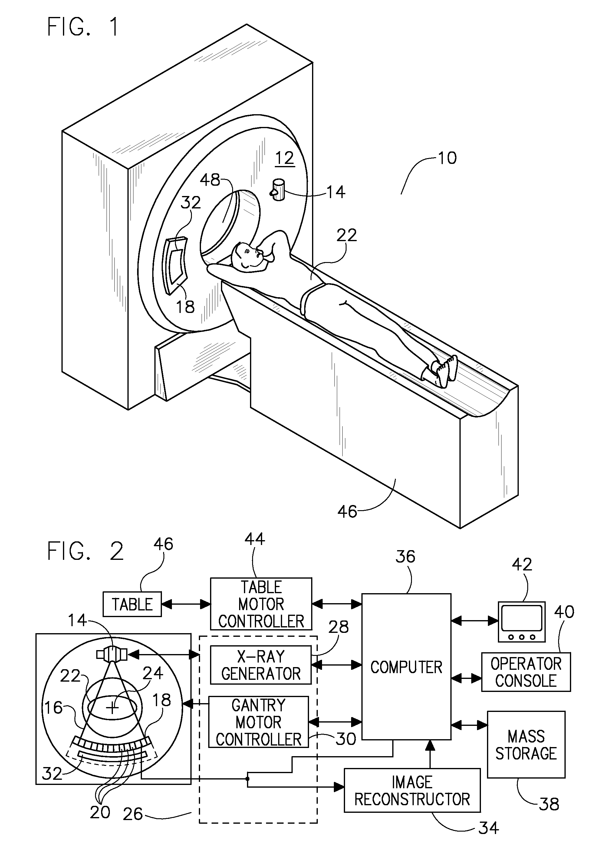
[0036]Referring to FIGS. 1 and 2, a computed tomography (CT) imaging system 10 is shown as including a gantry 12 representative of a “third generation” CT scanner. Gantry 12 has an x-ray source 14 that projects a beam of x-rays toward a detector assembly or collimator 18 on the opposite side of the gantry 12. Referring now to FIG. 2, detector assembly 18 is formed by a plurality of detector elements 20 and a data acquisition system (DAS) 32. The detector elements 20 sense the projected x-rays 16 that pass through an object or medical patient 22, and DAS 32 converts the data to digita...


PUM


Abstract

A modular x-ray source for an imaging system includes a structure forming a cavity and having a first wall and a second wall, at least one target positioned on the first wall within the cavity and configured to receive a first electron beam at a first spot position and a second electron beam at a second spot position, and a shielding material positioned on the second wall.

Description

BACKGROUND OF THE INVENTION[0001]Embodiments of the invention relate generally to diagnostic imaging and, more particularly, to a modular multispot x-ray source for use in an imaging system.[0002]Traditional x-ray imaging systems include an x-ray source and a detector array. X-rays are generated by the x-ray source, passed through and attenuated by an object, and are detected by the detector array. Hereinafter, the terms “subject” and “object” shall include anything capable of being imaged. The intensity of the attenuated beam radiation received at the detector array is typically dependent upon the attenuation of the x-ray beam by the object. Each detector element of the detector array produces a separate electrical signal indicative of the attenuated beam received by each detector element. The electrical signals are transmitted to a data processing system for analysis, which ultimately produces an image.[0003]Generally, as in a CT application, the x-ray source and the detector arra...

Claims


Application Information

Patent Timeline
Patent Type & Authority Applications(United States)
IPC IPC(8): H01J35/10H01J35/08
CPCG21K1/025H01J35/08H01J35/16H01J2235/068H01J2235/166H01J2235/1204H01J2235/1262H01J2235/163H01J2235/086H01J35/112
Inventor VERMILYEA, MARK E.CAO, YANGINZINNA, LOUIS PAULJACOBS, DENNIS M.ZHANG, XIZOU, YUN
Owner GENERAL ELECTRIC CO
Why Eureka
Try Eureka